


18
920-087-04
R Y W B GL GH C D1 D2 F1 F2
JP1
12345678
ON DIP
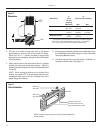
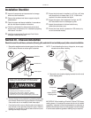
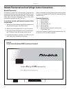
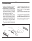
Remote Thermostat and Low Voltage Control Connections
To control the unit with a wall mounted thermostat follow
the steps below:
1) With the front cover removed locate the low voltage terminal
strip at the lower portion of the Smart Center.
2) Remove the jumper between the ‘GL’ and GH’ terminals.
3) The control is now confi gured for control by a wall thermo-
stat. The Smart Center will no longer control the unit.
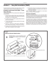
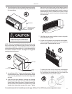
4) If desired the accessory escutcheon kit (PDXRT) is to be
used, install it over the existing control panel.
Note: To revert back to the Smart Center control of the unit replace
the jumper wire between the ‘GL’ and ‘GH’ terminals that was
removed in step 1.
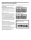
Thermostat Connections
C = Common Ground
W = Call for Heating
Y = Call for Cooling
R = 24V Power from Unit
GL = Call for Low Fan
GH = Call for High Fan
B = Reversing Valve Energized in heating mode
(PDH Models Only)
*If only one G terminal is present on thermostat connect to GL
for low fan or to GH for high fan operation.
Remote Thermostat
All Friedrich PD model PTAC units are factory confi gured to be
controlled by either the chassis mounted Smart Center or a 24V
single stage remote wall mounted thermostat. The thermostat
may be auto or manual changeover as long as the control
confi guration matches that of the PTAC unit.
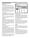
Figure 13
Control board with optional PDXRT escutcheon kit installed