


10
920-087-04
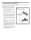
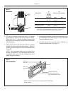
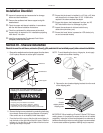
3. Drill two 3/16" holes through each side of the sleeve
approximately 4" from top and 4" from bottom of sleeve.
Screw four #10 x 1" screws (included) or appropriate
fasteners for your installation, through the holes in the sides
of the wall sleeve.
4. Apply sealant around the wall sleeve where it projects
through the inside and outside wall surfaces. Apply the
sealant to the screw heads or the tops of the fasteners used
in Step #3.
NOTE: When sealing the sleeve on the outside of the
building, be care ful NOT to let the sealant block the two
condensate drain holes or the four overfl ow slots at the
bottom fl ange of the sleeve.
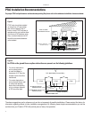
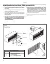
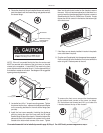
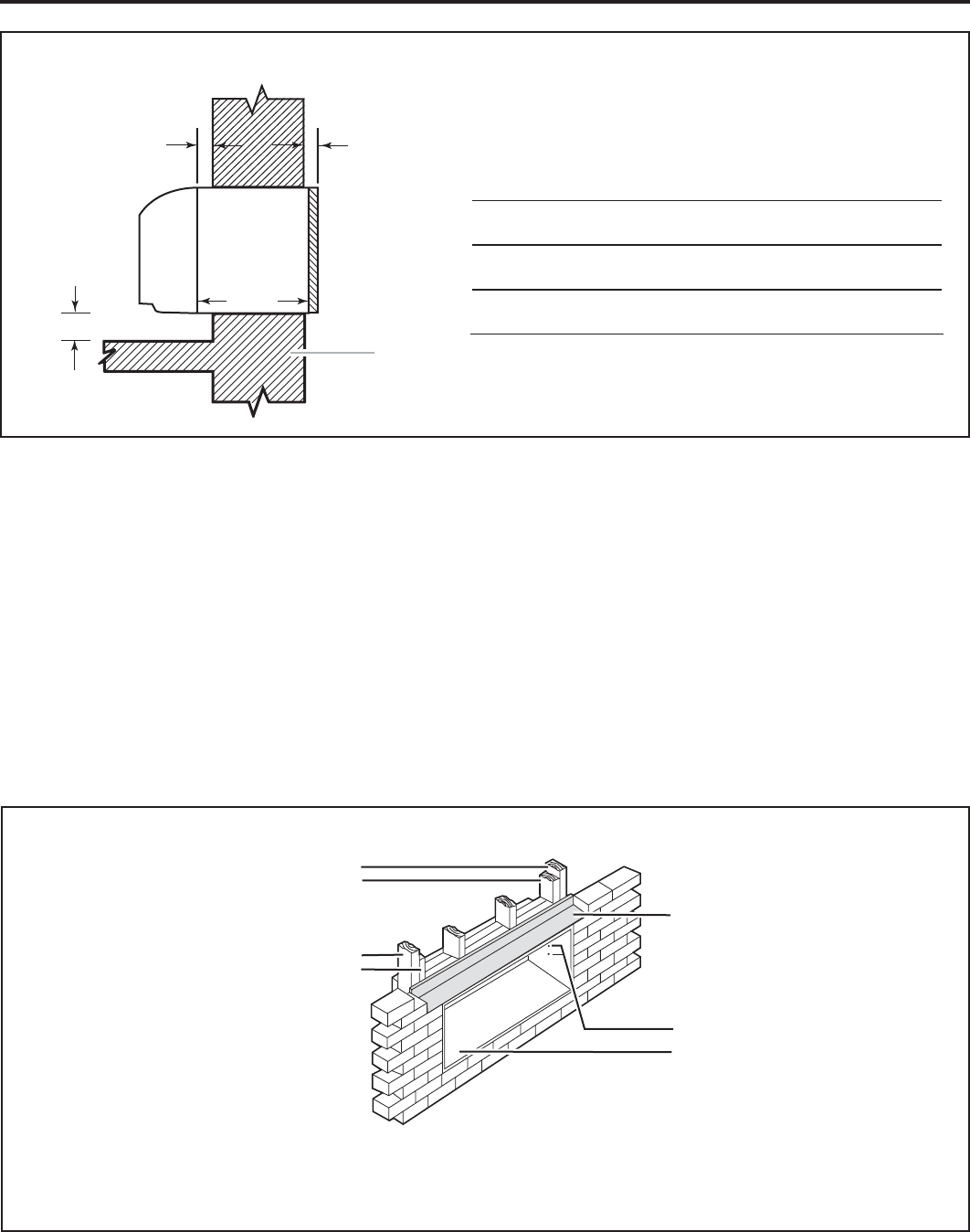
Figure 7
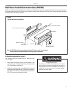
NOTE: Construct wall opening to comply with all applicable
building codes.
Main studs
Jack studs
Main studs
Jack studs
Lintel
Mounting screw holes
No holes in bottom of wall
sleeve unless drain kit is used
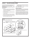
5. If the chassis and exterior grille are to be installed later, leave
the weatherboard and center support in place, otherwise
remove and dispose of them.
6. Provide a support lintel if the wall sleeve is installed in a
concrete or masonry wall. (See Figure 7.)
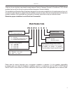
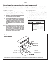
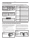
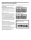
13¾ "
(35 cm)
A
B
¼"
(6.4 cm)
min.
Wall
Dimensions
Figure 6
Dimension*
A
Allow
for wall
fi nishing
B
Allow for fl oor fi nishing
(Minimum) Min. Max
No Accessories ¼"
(6.4 mm)*
¼"
(6.4 mm) ---
With Subbase 1¾"
(4.5 cm)
3½"
(8.9cm)
5"
(12.7cm)
With Lateral Duct ¾"
(1.9 cm)
¼"
(6.4 mm) ---
* If more than one accessory is to be used, use the maximum
dimension. If the wall thickness is more than 13¾" (35cm) -
(A + ¼" [6.4 mm]), a sleeve extension must be used.
L i n t e l I n s t a l l a t i o n