


16
920-087-04
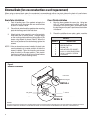
Digital Control User Input Confi guration
The adjustable control dip switches are located at the lower left hand portion of the digital Smart Center. The inputs are only visible
and accessible with the front cover removed from the PTAC.
Dip Switch Setting
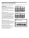
1) Electronic Temperature Limiting – Switches 1-4
The digital control is set from the factory to allow a tempera-
ture range between 60°F and 90°F in both heating and cooling
mode. Dip Switches 1-4 can be used to set high and low limits
for either heating or cooling or both.
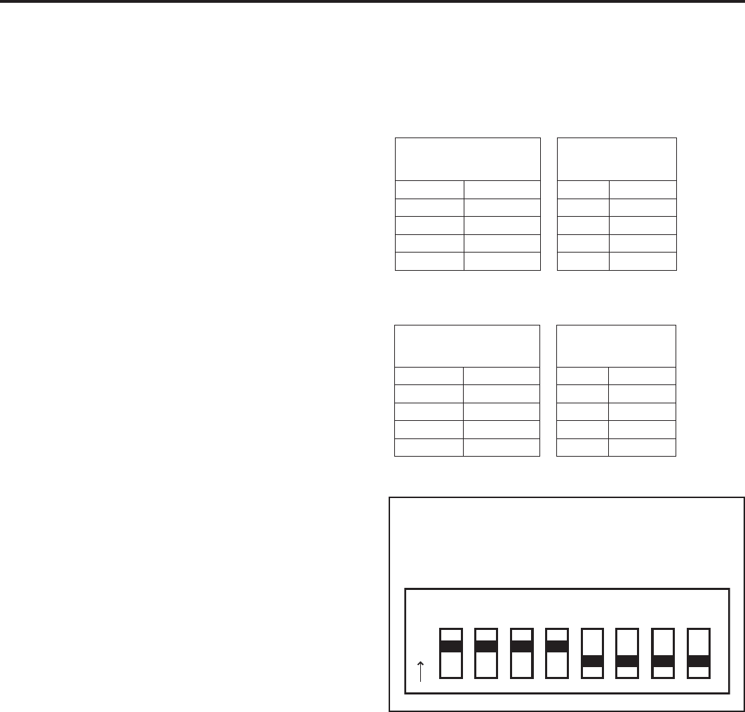
From the factory all four switches are in the up ‘ON’ position.
The charts to the right show the available electronic limiting
ranges.
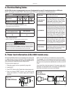
2) Fan Cycle Control – Switch 5
All PTACs are shipped from the factory with Dip Switch 5 in the
‘OFF’ position to cycle the fan only when there is a demand for
the compressor or heater. As an option the fan may be set to
‘continuous’ mode by switching Dip Switch 5 to ‘ON’ position to
run the fan continuously while the unit is powered on.
To ensure that the room temperature is maintained evenly while
in fan cycle mode the Even Temp Load Anticipation feature is
enabled. Quiet Fan Delay is also enabled in fan cycle mode to
lessen the acoustical change between compressor start up and
shut off by running the fan for 5 seconds before each demand
cycle, and 30 seconds after cooling or 15 seconds after heating
cycles.
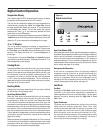
3) Room Freeze Protection – Switch 6
Units are shipped from the factory with the room freeze protection
disabled. Room Freeze Protection can be switched on at the
owner’s preference by moving Dip Switch 6 to ‘ON’. This feature
will monitor the indoor room conditions and in the event that the
room falls below 40°F the unit will cycle on high fan with the
electric heater. This occurs regardless of mode.
4) Emergency Heat Override – Switch 7
In the unlikely event of a compressor failure a heat pump unit
may be switched to operate in only the electric heat mode until
repairs can be made. Moving Dip Switch 7 to ‘ON’.
Note: PTAC must be disconnected from power supply
when making any confi guration changes.
Temperature
Range
Dip
Switch
Low High 3 4
60 90 On On
63 90 On Off
66 90 Off Off
69 90 Off On
Cooling Range Switches 3 & 4
Heating Range Switches 1 & 2
Temperature
Range
Dip
Switch
Low High 1 2
60 90 On On
60 87 Off On
60 84 Off Off
60 81 On Off
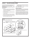
Figure 11
Factory Dip Switch Confi guration
12 34 56 78
O
N