


21
920-087-04
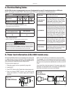
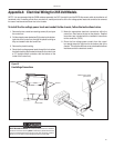
Appendix A: Electrical Wiring for 265 Volt Models
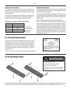
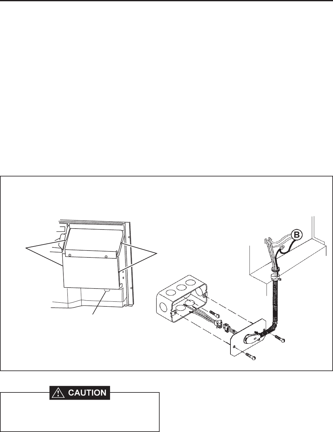
1. Remove the four control box retaining screws (A) and open
the control box.
2. Pull the chassis power lead wires (B) (located on the bottom-
right side of the control box) through the plastic bushing so
they are located inside the control box.
3. Remove the plastic bushing.
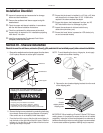
4. Route the line voltage power leads through the hole where
the plastic bushing was located, and secure its conduit (use
a 1/2" straight conduit connector, with the locknut on the
inside of the control box.)
NOTE: It is recommended that the PXSB subbase assembly, the PXCJ conduit kit and the PXDS disconnect switch be installed on all
hardwired units. If installing a fl ush-fl oor mounted unit, make provisions for all the line voltage power leads and conduit to be removed
for ease of maintenance and service to the chassis.
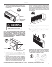
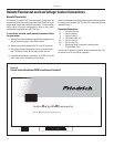
Line Voltage Connections
Figure 15
5. Make the appropriate electrical connections within the
control box, then secure the box on the chassis. Detailed
instructions are included with the installation instructions
for the conduit kit (PXCJ).
6. Route the line voltage power conduit from the control
box straight down the right front to the bottom side of the
chassis. This will allow the front cover to be installed without
interference with the electrical conduit.
To install the line voltage power leads and conduit to the chassis, follow the instructions below.
Inside back of control
panel cover.
Screws
Screws
Fuse holder
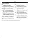
ELECTRIC SHOCK HAZARD! Turn off electric power before service or installation.
All electrical connections and wiring MUST be installed by a qualifi ed electrician and
conform to the National Electrical Code and all local codes which have jurisdiction.
Failure to do so can result in property damage, personal injury and/or death.