– 25 –
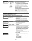
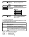
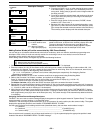
XX OUTPUT TYPE
DELETE 0
Output Type
0 = delete
1 = relay on 4204/4229
module
2 = Powerline Carrier device
(X-10)
[∗] to continue
Select whether this is a relay or a Powerline Carrier (X-10)
device.
If Powerline Carrier is selected, go to “A” prompt.
If relay is selected, skip to “B” prompt.
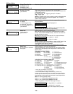
“A”
XX UNIT No.
yy
Unit Number
01-16 = predefined address
[∗] to continue
(prompt appears if X-10 is selected)
Enter the unit code (set at the device) and press [∗].
The system returns to the Output Number prompt.
“B”
XX MODULE ADDR
07-15 yy
Module Address
07-15 = predefined address
[∗] to continue
(prompt appears if relay is selected)
Enter the predefined address for this module as listed below.
Make sure the module’s DIP switches are set to the selected
address.
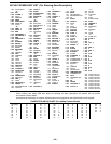
Module Addresses
Address Module
07 1st 4229 (with zones 09-16)
08 2nd 4229 (with zones 17-24)
09
†
3rd 4229 (with zones 25-32)
10
†
4th 4229 (with zones 33-40)
11
†
5th 4229 (with zones 41-48)
12 1st 4204
13 2nd 4204
14
†
3rd 4204
15
†
4th 4204
† These addresses apply to FA168CPS only.
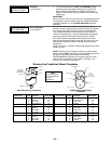
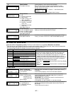
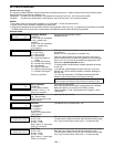
XX REL POSITION
1-4 zz
Relay Position
1-4 = relay position
[∗] to continue
This is the actual (or physical) relay number with respect to the
Relay Module upon which it is located. For 4204 modules, relay
numbers are 1-4. For 4229 modules, relay numbers are 1-2.
The system returns to the Output Number prompt for
programming the next device.
∗
∗∗
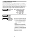
∗80 OUTPUT FUNCTION MENU MODE
(press
∗
∗∗
∗
80 while in Programming mode) The Output Definition Worksheet is on page Error! Bookmark not defined..
Use this mode to program output function definitions (up to 48 functions) that provide automated control of any of the output
devices, based on events occurring on individual zones or zones with certain zone types.
Each output definition is identified
by an output function number, and includes the following components:
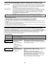
Output Definition Components
Component Description
Output Function No. A reference number that defines an output’s characteristics.
Activated By Determines whether the initiating event occurs on a zone, a zone list, or a zone type.
Event Event that triggers the output action. Can be an event occurring on a specific zone number or a
zone list, or a specific zone type.
Partition If the output is activated by zone type, this defines the partition in which the programmed event is
to cause the device action.
Output Action Defines the action of the relay/X-10 device when the defined event occurs. Can close for 2
seconds, stay closed until reset, continuously pulse (1-second close-open-close-open, etc.),
toggle the device state, or activate for a defined duration (set in data field *177).
Output No. Assigns this function to a specific output number (defined in *79 Menu Mode). This is the output
number that will perform this function upon the triggering event. Note that each defined function is
associated with only one output number. This means that if more than one output device needs to
perform this particular function, you need to define another output function number with the same
attributes, but assign the appropriate output number. (i.e. output devices can be assigned more
than one function number, but each function number can only be assigned a single output
number.
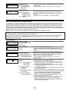
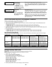
For example, if you want to pulse a strobe light upon fire alarms on zone 4 using a relay mapped to output number 2 (as
programmed in *79 Menu Mode), program the following in *80 Menu Mode:
Prompt Entry
Output Funct. # = 01 (assuming this is the first output function)
Activated By: = 3 (zone number)
Enter Zn No. = 04 (requires 2-digit zone numbers)
Output Action = 3 (continuous pulse)
Output Number = 02 (device mapped in *79 Menu Mode)


