– 10 –
OUTPUT AND SYSTEM SETUP (
✱
77 –
✱
93)
∗
∗∗
∗77
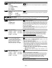
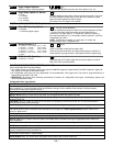
Daylight Savings Time Start/End
Month
0 = Disabled
1-9 = January-September
(1 = Jan, 2 = Feb, etc)
#+10 = October
#+11 = November
#+12 = December
| [3][11]
Enter the start and end month for daylight savings time, if applicable to
the region.
∗
∗∗
∗78
Daylight Savings Time Start/End
Weekend
0 = disabled 4 = fourth
1 = first 5 = last
2 = second 6 = next to last
3 = third 7 = third to last
| [2][1]
Enter the start and end weekend for daylight savings time, if applicable
to the region.
∗
∗∗
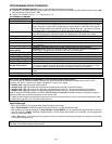
∗79, *80, *81, *82 Menu Modes
These are Menu Mode commands, not data fields, for Output Device Mapping, Output Programming, Zone List Programming,
and Alpha Programming respectively. See page 3 and their respective sections for procedures.
∗
∗∗
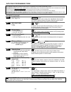
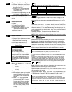
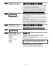
∗84
Auto Stay Arm
0 = no
1 = partition 1 only
2 = partition 2 only
3 = both partitions
[FA168CPS: 3; FA148CP: 1]
If enabled, the system will automatically change AWAY mode to STAY
mode if the entry/exit door is not opened and closed within the exit
delay time after a user arms in AWAY mode from a wired keypad (non-
RF device). An Opening report followed by an Armed Stay report is
sent to the Central Station.
If the door is opened and closed within the exit delay period, the
system remains in AWAY mode.
Any RF device that arms the system AWAY overrides this feature and
the system remains armed AWAY.
∗
∗∗
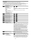
∗85
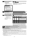
Cross Zone Timer
0 = 15 secs 6 = 2-1/2 min #+12 = 8 min
1 = 30 secs 7 = 3 min #+13 = 10 min
2 = 45 secs 8 = 4 min #+14 = 12 min
3 = 60 secs 9 = 5 min #+15 = 15 min
4 = 90 secs #+10 = 6 min
5 = 2 min #+11 = 7 min
[0]
Sets the maximum amount of time in which two cross zones must be
tripped in an armed system to send an alarm message to the Central
Station. If only one cross zone is tripped during this time, a trouble
message (CID code 380) for that zone is sent to the Central Station.
This option not for use in UL installations.
Assign cross zones on zone list 4, using *81 Menu mode.
NOTE: Cross zoning takes effect only after Exit Delay expires.
∗
∗∗
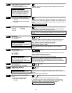
∗86
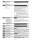
Cancel Verify Keypad Display
0 = no “alarm canceled” display
1 = display “Alarm Canceled” when
system is disarmed after an alarm has
occurred. (To clear the “ALARM
CANCELED” display, the user must
enter the security code + OFF again.)
[1]
This feature causes a “ALARM CANCELED” display on the LCD
keypad under the following conditions:
• After the kissoff of the cancel message to the Central Station,
indicating a successful transmission.
• When an alarm is successfully canceled before the Central Station
received the Alarm message. E.g., if an alarm is incorrectly triggered
and the user presses code + OFF before the dial delay time has
expired, the message will never go out to the CS.
•
When the Cancel report is not enabled and the system is disarmed:
a. before dialer delay expires (alarm report not sent) message
“Alarm Canceled” is displayed.
b. after dialer delay expires message “Alarm Canceled” is not
displayed
.
∗
∗∗
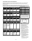
∗87
Misc. Fault Delay Time
0 = 15 secs 6 = 2-1/2 min #+12 = 8 min
1 = 30 sec 7 = 3 min #+13 = 10 min
2 = 45 secs 8 = 4 min #+14 = 12 min
3 = 60 secs 9 = 5 min #+15 = 15 min
4 = 90 secs #+10 = 6 min
5 = 2 min #+11 = 7 min
[0]
(used with Configurable Zone Types “digit 6”)
Used with zones assigned to a configurable zone type with fault delay
on (configurable zone type digit “6”), and sets a zone response time of
15 seconds to 15 min. It can be assigned to zones with sensors that
provide a trouble indication when an oil tank is low, or similar
applications for critical condition monitoring where a non-alarm
response is desired.
UL: may only be used on non-burglar alarm/ non-fire alarm zones when used
in fire and/or UL burglar alarm installation


