


7
NS SPLIT INSTALLATION MANUAL
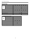
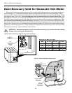
Rated Voltage
HWA Ext Total Min Max
Model Voltage Min/Max
Pump Loop Unit Circ Fuse/
MCC RLA LRA FLA FLA FLA Amp HACR
026 208-230/60/1 197/253 16.0 10.2 52.0 0.4 5.4 16.0 18.6 25
038 208-230/60/1 197/253 26.0 16.6 82.0 0.4 5.4 22.4 26.6 40
049 208-230/60/1 197/253 33.0 21.1 96.0 0.4 5.4 26.9 32.2 50
064 208-230/60/1 197/253 40.0 25.6 118.0 0.4 5.4 31.4 37.8 60
072 208-230/60/1 197/253 42.5 27.2 150.0 0.4 5.4 33.0 39.8 60
Rated Voltage of 208-230/60/1.
Rev.: 02/20/07
HACR circuit breaker in USA only.
Min/Max Voltage of 197/253.
All fuses Class RK-5.
Compressor
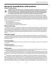
General
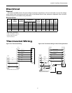
Be sure the available power is the same voltage and phase as that shown on the unit serial plate. Line and low voltage
wiring must be done in accordance with local codes or the National Electric Code, whichever is applicable. See unit electri-
cal data for fuse or cicuit breaker sizing information.
Electrical Data
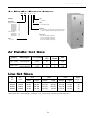
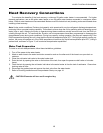
Thermostat Wiring
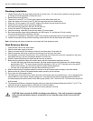
Figure 12b: Thermostat Wiring for Dual Fuel Applications
Figure 12a: Thermostat Wiring
Electrical
Y1
Y2
O
R
C
C
R
Air Handler
Thermostat
24 VAC
Common Common
24 VAC
Reversing Valve
2nd Stage Compressor
1st Stage Compressor
Y1
Y2
O
R
C
G
G
Fan
W
W
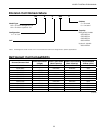
Typical EZ Wiring Diagram
P1
Air Handler transformer must be at least 75 VA.
L
Lo
Fault Signal
Envision Split
Y1
Y2
O
R
C
L
C
R
Fossil Fuel
Furnace
Thermostat
24 VAC
Common Common
24 VAC
Fault Signal
Reversing Valve
2nd Stage Compressor
1st Stage Compressor
Y1
Y2
O
R
C
LO
G
G
Fan
W
W
Auxiliary Heat Relay
Note: Field installed DPST dual fuel relay
(Required for dual fuel installation)
Auxiliary Heat Relay
P2
P1
Shut
Down
= chassis
Envision Split
Auxiliary
Heat Relay