


26
NS SPLIT INSTALLATION MANUAL
High voltage is correct and matches nameplate.
Fuses, breakers and wire size correct.
Low voltage wiring complete.
Piping completed and water system cleaned and ushed.
Air is purged from closed loop system.
Isolation valves are open, water control valves or loop pumps wired.
Condensate line open and correctly pitched.
Transformer switched to 208V if applicable.
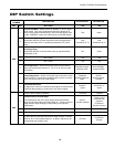
DIP switches are set correctly.
DHW pump switch is “OFF” unless piping is completed and air has been purged.
Blower rotates freely.
Blower speed correct.
Air lter/cleaner is clean and in position.
Service/access panels are in place.
Return air temperature is between 50-80ºF heating and 60-95ºF cooling.
Check air coil cleanliness to insure optimum performance. Clean as needed according to maintenance guidelines.
To obtain maximum performance the air coil should be cleaned before startup. A 10-percent solution of dishwasher
detergent and water is recommended for both sides of coil, a thorough water rinse should follow.
Startup Steps
Notes: Complete the Equipment Start-Up/Commissioning Check Sheet during this procedure. Refer to thermostat operat-
ing instructions and complete the startup procedure.
1. Initiate a control signal to energize the blower motor. Check blower operation.
2. Initiate a control signal to place the unit in the cooling mode. Cooling setpoint must be set below room temperature.
3. First stage cooling will energize after a time delay.
4. Be sure that the compressor and water control valve or loop pump(s) are activated.
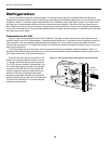
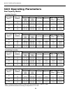
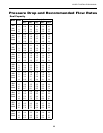
5. Verify that the water ow rate is correct by measuring the pressure drop through the heat exchanger using the P/T
plugs and comparing to unit capacity data in specication catalog.
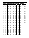
6. Check the temperature of both the supply and discharge water (see page 24).
7. Check for an air temperature drop of 15°F to 25°F across the air coil, depending on the fan speed and entering water
temperature.
8. Decrease the cooling set point several degrees and verify high-speed blower operation.
9. Adjust the cooling setpoint above the room temperature and verify that the compressor and water valve or loop pumps
deactivate.
10. Initiate a control signal to place the unit in the heating mode. Heating set point must be set above room temperature.
11. First stage heating will energize after a time delay.
12. Check the temperature of both the supply and discharge water (see page 24).
13. Check for an air temperature rise of 20°F to 35°F across the air coil, depending on the fan speed and entering water
temperature.
14. If auxiliary electric heaters are installed, increase the heating setpoint until the electric heat banks are sequenced on.
All stages of the auxiliary heater should be sequenced on when the thermostat is in the Emergency Heat mode.
Check amperage of each element.
•
•
•
•
•
•
•
•
•
•
•
•
•
•
•
•
Unit Startup
Before Powering Unit, Check The Following: