


5
NS SPLIT INSTALLATION MANUAL
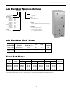
Air Handler Installation
Air handlers used with dual capacity units must be capable of operating with a minimum of 2 blower speeds. Refer to the
manufacturer’s instructions for the blower coil unit for details on installing the air handling portion of the system. All blower
coil units/air coils must be installed as specied by the manufacturer’s installations instructions. However, the following rec-
ommendations should be considered to minimize noise and service problems.
An air lter must always be installed upstream of the air coil on the return air side of the air handler of furnace. If there is
limited access to the lter rack for normal maintenance, it is suggested that a return air lter grille be installed. Be sure that
the return duct is properly installed and free of leaks to prevent dirt and debris from bypassing the lter and plugging the air
coil.
Ensure that the line set size is appropriate to the capacity of the unit (refer to page 9). Line sets should be routed as di-
rectly as possible, avoiding unnecessary bends or turns. All wall penetrations should be sealed properly. Line set should not
come into direct contact with water pipes, oor joists, wall studs, duct work, oors, walls and brick. Line set should not be
suspended from joists or studs with a rigid wire or strap which comes into direct contact with the tubing. Wide hanger strips
which conform to the shape of the tubing are recommended. Isolate hanger straps from line set insulation by using metal
sleeves bent to conform to the shape of insulation. Line set insulation should be pliable, and should completely surround the
refrigerant line.
Notes: Improper installation of equipment may result in undesirable noise levels in the living areas.
Connection to Air Coil
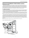
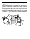
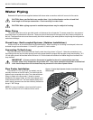
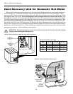
Figures 1 and 2 illustrate typical Envision Split installations. The table on page 9 shows typical lineset diameters and
maximum length. Linesets over 60 feet are not recommended. If the lineset is kinked or deformed and cannot be reformed,
the bad section of pipe should be replaced. A restricted lineset will affect unit performance. As in all R-410A equipment, a
reversible liquid line lter drier is required to insure all moisture is removed from the system. This drier should be replaced
whenever “breaking into” the system for service. All linesets should be insulated with a minimum of 1/2” closed cell insula-
tion. All exterior insulation should be painted with UV resistant paint or covering to insure long insulation life.
Figure 1: Typical Split System Application - Remote Blower Coil
General Installation Information (cont.)
Lineset
ToAir Handler
Insulated
Suction Line
Return
Duct
Low
Voltage Wire
Disconnect
RemoteAir Handler
(Maximum Recommended Distance is
50' Between Units)
Condensate Drain
(must be trapped)
Supply
Duct
A
i
r
Han
dl
e
r