


16
NS SPLIT INSTALLATION MANUAL
Startup
The unit will not operate until all the inputs and safety controls
are checked for normal conditions. At rst power-up, a four-minute
delay is employed before the compressor is energized.
Component Sequencing Delays
Components are sequenced and delayed for optimum space
conditioning performance.
Accessory Relay
An accessory relay on the control board allows for eld
connection of solenoid valves, electronic air cleaners, etc. The
accessory relay has a normally open output and a normally closed
output.
Short Cycle Protection
The control employs a minimum "off" time of four minutes to
provide for short cycle protection of the compressor.
Shutdown Mode
A 24VAC common signal to the “shutdown” input on the control
board puts the unit into shutdown mode. Compressor, hot water
pump and fan operation are suspended.
Safety Controls
The Envision control receives separate signals for a high
pressure switch for safety, a low pressure switch to prevent loss
of charge damage, and a low suction temperature thermistor for
freeze sensing. Upon a continuous 30-second measurement of
the fault (immediate for high pressure), compressor operation is
suspended, the appropriate lockout LED begins ashing. (Refer to
the "Fault Retry" section below.)
Testing
The Envision control allows service personnel to shorten most
timing delays for faster diagnostics. (Refer to the Field Selection
DIP switch SW2-1 on page 21.)
Fault Retry
All faults are retried twice before nally locking the unit out. An
output signal is made available for a fault LED at the thermostat.
The “fault retry” feature is designed to prevent nuisance service
calls.
Diagnostics
The Envision control board allows all inputs and outputs to be
displayed on the LEDs for fast and simple control board diagnosis.
(Refer to the Field Selection DIP Switch SW2-1 on page 21.)
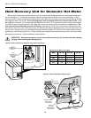
Hot Water High Limit
(Domestic Hot Water Option)
This mode occurs when the hot water input temperature is at
or above 130°F for 30 continuous seconds. The DHW limit status
LED on the unit illuminates and the hot water pump de-energizes.
Hot water pump operations resume on the next compressor cycle
or after 15 minutes of continuous compressor operation during the
current thermostat demand cycle.
Hot Water Justication
Since compressor hot gas temperature is dependant on loop
temperature in cooling mode, loop temperatures may be too low
to allow proper heating of water. The control will monitor water and
refrigerant temperatures to determine if conditions are satisfactory
for heating water. The DHW limit status LED on the unit illuminates
when conditions are not favorable for heating water.
Heating Operation
Heat, 1st Stage (Y1)
The fan motor is started on low speed immediately (PSC
ON), the loop pump is energized 5 seconds after the “Y1” input
is received, and the compressor is energized on low capacity 10
seconds after the “Y1” input. The fan is switched to medium speed
15 seconds after “Y1” input (ECM only). The hot water pump is
cycled 30 seconds after the "Y1" input.
Heat, 2nd Stage (Y1,Y2) Dual Capacity Units
The second stage compressor will be activated 5 seconds
after receiving a “Y2” input as long as the minimum rst stage
compressor run time of 1 minute has expired. The ECM blower
changes from medium to high speed 15 seconds after the “Y2” input.
The Comfort Alert will delay the second stage compressor
until 5 seconds after it receives a “Y2” from the board.
Heat, 3rd Stage (Y1,Y2,W) Dual Capacity Units
The hot water pump is de-energized which directs all heat
to satisfy the thermostat. The 1st stage of resistance heat is
energized 10 seconds after “W” input, and with continuous 3rd
stage demand, the additional stages of resistance heat engage
sequentially every 5 minutes.
Emergency Heat (W only)
The fan is started on high speed, and the rst stage of
resistance heat is energized 10 seconds after the "W" input.
Continuing demand will engage the additional stages of
resistance heat sequentially every 2 minutes.
Cooling Operation
In all cooling operations, the reversing valve directly
tracks the “O” input. Thus, anytime the “O” input is present,
the reversing valve will be energized.
Cool, 1st Stage (Y1,O)
The blower motor and hot water pump are started immediately,
the loop pump(s) is energized 5 seconds after the “Y1” input is
received. The compressor will be energized (on low capacity for
Dual Capacity units) 10 seconds after the “Y1” input. The ECM
blower will shift from low to medium speed 15 seconds after the
“Y1” input (85% of medium speed if in dehumidication mode).
Cool, 2nd Stage (Y1, Y2, O) Dual Capacity Units
The second stage compressor will be activated 5 seconds
after receiving a “Y2” input as long as the minimum rst stage
compressor run time of 1 minute has expired. The ECM blower
changes to high speed 15 seconds after the “Y2” input (85% of
Microprocessor Control