


20
NS SPLIT INSTALLATION MANUAL
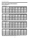
The Envision series comes with a holding charge. The charge must be adjusted in the eld based on performance.
Refrigeration piping on the split consists of installing a brazed copper line set between the blower coil unit and the unit’s split
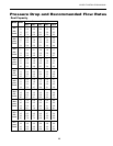
compressor section. To select the proper tube diameters for the installation, refer to the table on page 9. Line sets over 60
feet long are not recommended because of oil return and pressure drop problems. The suction line must always be insu-
lated. Handle and route the line sets carefully to avoid kinking or bending the tubes. If the line set is kinked or distorted and
it cannot be formed back into its original shape, the bad portion of the pipe should be replaced. A restricted line set will affect
the performance of the system.
Connection to Air Coil
Figures 1 and 2 illustrate typical Envision Split installations. The table on page 9 shows typical lineset diameters and
maximum length. As in all R-410A equipment, a reversible liquid line lter drier is required to insure all moisture is removed
from the system. This drier should be replaced whenever “breaking into” the system for service. All linesets should be
insulated with a minimum of 1/2” closed cell insulation. All insulation should be painted with UV resistant paint or covering to
insure long insulation life.
Fasten the copper line set to the blower coil unit as instructed by the coil installation instructions shown in Figure 14.
Nitrogen should be bled through the system at 2 to 3 PSI to prevent oxidation inside the refrigerant tubing. Use a low silver
phos-copper braze alloy on all brazed connections.
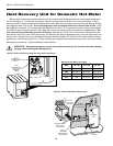
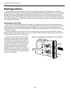
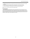
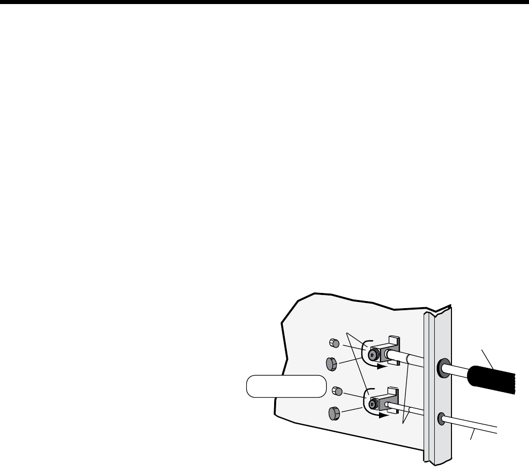
Braze line set to the service valve stubs on the
inside front of the split cabinet as shown in Figure
13. Nitrogen should be bled through the system at
2 to 3 PSI to prevent oxidation contamination. Use
a low silver phos-copper braze alloy on all brazed
connections. Envision split units are shipped with
a factory charge and service valves are not to be
opened until the line set has been leak tested,
purged and evacuated. Schrader cores should be
removed before brazing. A heat sink should be used
on the service valves and TXV to prevent damage
caused by excessive heat.
Refrigeration
Replace caps after
opening system
Service ports for
attaching refrigerant
gauges
Insulated
Suction Line
Braze
Connection
Liquid
Line
ccw
ccw
Figure 13: Typical Split System Refrigerant Line Connections