


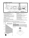
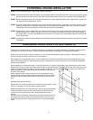
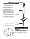

When planning your installation, it will be necessary to select the proper length of vent pipe for your particular requirements. It
is important to note when passing through a wall, the maximum allowable wall thickness is 10-inches (254mm), 1 ½ inches
clearance to combustibles must be maintained. Select the amount of vertical rise desired for “vertical-to-horizontal” type
installations. To determine the length of vent pipe required for vertical installations, measure the distance from the appliance
flue outlet to the ceiling, the ceiling thickness, the vertical rise through the attic or second story, and allow for sufficient vent
height above the roofline. For two story applications, A firestop is required at each floor level. If an offset is needed in the attic,
additional pipe and elbows will be required. To connect the venting system to the appliance flue outlet, a twist-lock adapter is
built into the appliance at the factory.
HORIZONTAL INSTALLATION
STEP 1. Set the appliance in the desired location. Check to determine if wall studs or roof rafters are in the way when the
venting system is attached. If this is the case, you may want to adjust the location of the appliance.
STEP 2. Direct vent pipe and fittings are designed with special twist-lock connections. Assemble the desired combination of
black pipe and elbows to the appliance adapter with pipe seams oriented towards the wall or floor, as much out of
view as possible.
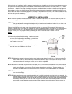
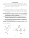
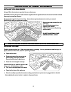
Place a bead of Mil-Pac on the outer edge of the inner exhaust pipe (non-flared end). Place a bead of high temperature
silicone on the male edge of the outer pipe. Push the pipe sections completely together, then twist-lock one section clockwise
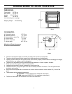
approximately one-quarter turn, until the two sections are fully locked. The female locking lugs will not be visible from the
outside, on black pipe. They may be located by examining the inside of the female ends as shown in FIG-10.
NOTE:
(1) Twist-lock procedure: four indentations, located on the female
end of the pipes and fittings, are designed to slide straight onto
the male ends of adjacent pipes and fittings, by orienting the
four pipe indentations so they match and slide into the four
entry slots on the male end.
(2) Horizontal runs of vent pipe must be supported every three
feet. Wall straps are available for this purpose.
FIG. 10
FIG.10
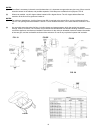
STEP 3. With the pipe attached to the stove into the correct location, mark the wall for a 10 inch x 10 inch square hole. The
center of the square hole should match the centerline of the horizontal pipe. Cut and frame the 10-inch x 10-inch
hole in the exterior wall where the vent will be terminated. If the wall being penetrated is constructed of non-
combustible material i.e. masonry or concrete, a 7-inch hole is acceptable.
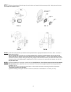
STEP 4. Position the horizontal vent termination in the center of the 10-inch square hole, and attach to the exterior wall with
the four screws provided. Before attaching the Vent Termination to the exterior wall, run a bead of non-hardening
mastic around the edges, so as to make a seal between the termination and the wall. The arrow on the vent
termination should be pointing up, insure that the proper clearances to combustible materials are maintained.
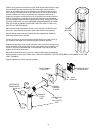
STEP 5. Before connecting the horizontal run of the vent pipe to the vent termination, slide the black decorative wall thimble
cover over the vent pipe.
STEP 6
. Slide the appliance and vent assembly towards the wall, carefully inserting the vent pipe into the cap assembly. It is
important that the vent pipe extend into the vent cap a sufficient distance with a minimum of 1 ¼inch overlap. Secure
the connection between the vent cap pipe and the vent cap by attaching the two sheet metal straps extending from
the vent cap assembly into the outer wall of the vent pipe. Use the two sheet metal screws provided to connect the
straps to the vent pipe. Bend any remaining portion of the sheet metal straps back towards the vent cap, so the
decorative wall thimble FIG-13 will conceal it.
7