


CATHEDRAL CEILING INSTALLATION
STEP 1. Follow installation steps 1 and 2 under Vertical Termination.
STEP 2. Using the plumb bob, mark the centerline of the venting system on the ceiling and drill a small hole through the ceiling
and roof at this point. From the roof, locate the drill hole and mark the outline of the “Cathedral Ceiling Support Box”.
STEP 3. Remove shingles or other roof coverings as necessary to cut the rectangular hole for the “Support Box”. Cut the hole
1/8” larger than the “Support Box” outline.
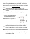
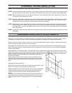
STEP 4. Lower the “Support Box” through the hole in the roof until the bottom of the “Support Box” protrudes at least 2-inches
below the ceiling.(FIG-20), align the “Support Box“ both vertically and horizontally with a level. Temporarily tack the
“Support Box” in the place through the inside walls and into the roof sheathing.
STEP 5. Using tin snips, cut the “Support Box” from the top corners down to the roofline, and fold the resulting flaps over the
roof sheathing.(FIG-21). Before nailing it in to the roof, run a bead of non-hardening mastic around the top edges of
the “Support Box”, to make a seal between the box and the roof. Clean out any combustible material from the inside
of the “Support Box”.
STEP 6. Complete the cathedral ceiling installation by following the same procedures outlined in Steps 4 through 9 for “Vertical
Termination”.
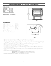
SHERWOOD INDUSTRIES LTD VENTING KITS
Inspect this kit to ensure this kit is complete and there is no damage to any of the components. If damage is present contact
your dealer or your courier company. If some components are missing or damaged do not attempt the installation.
Decide on a location for the unit that will meet any or all, local code requirements. Refer to sections in this manual. Deciding
Were To Locate Your Stove, and Planning Your Installation.
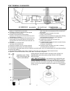
Set the appliance in the desired location. Check to determine if any wall studs, electrical wiring or plumbing pipes are in the
way of the venting system as it passes through the wall. If obstructions are found in the wall it may be required to adjust the
location of the appliance.
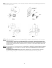
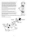
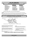
Set the appliance in the desired location. Temporarily place the 24” section of pipe (without the crimped end) on the unit and
install the 90° elbow pointing in the direction that the vent will exit the structure. Project a level line from the center point of the
elbow. Using this center point, scribe a 10” hole or square on the wall. Cut the hole out on both the interior and exterior wall
surfaces. Install the wall thimble and secure this thimble on both the inner
and outer wall surfaces.
With the appliance still in place install the 24” horizontal section on the
elbow and let this section of pipe protrude through the exterior wall. Mark
this pipe so that it is flush with the exterior surface and cut this section of
pipe.
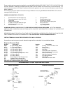
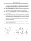
Dismantle the outer pipe sections.
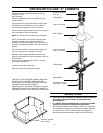
Remove the 4” flue collar from the unit and remove any lose sealant, install
the new 4” diameter x 5” high flue collar provided in this kit.
Attach the flexible liner to the vent termination cap by placing a small bead
of high temperature silicone on the vent terminal and slide the flex liner
onto the vent terminal and secure with 3 sheet metal screws evenly
spaced.
Dress the flex liner through the wall thimble and attach the vent terminal to
the outside of the house using 4 wood screws provided. (The use of non-
hardening mastic should be used around the vent to ensure a watertight
seal.)
11