


26
ELECTRICAL REQUIREMENTS:
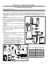
The ENVIRO EG40 will operate without electrical power. This model has a millivolt gas control, which
uses the pilot ame to generate enough electricity to operate the main burners. The appliance is equipped
with a blower and must be electrically connected and grounded in accordance with local codes or in
the absence of local codes, with the current CSA C22.1 CANADIAN ELECTRICAL CODE Part 1, SAFETY
STANDARDS FOR ELECTRICAL INSTALLATIONS, OR THE NATIONAL ELECTRICAL CODE ANSI / NFPA 70
in the U.S.
WARNING: Electrical grounding instructions. This
appliance is equipped with a three-prong (grounding)
plug for your protection against shock hazard, and
must be plugged directly into a properly grounded
three-prong outlet.
DO NOT cut or remove the grounding prong from
this plug.
CAUTION: Label all wires prior to disconnection
when servicing controls. Wiring errors can cause
improper and dangerous operation. Verify proper
operation after servicing.
NOTES:
• Operation of the fan increases the efciency and
the heat output of the appliance.
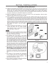
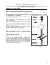
• The thermostat connects to the two purple wires in
the harness
• Control panel light uses a 7 Watt max. bulb
• If the unit is installed in a Mobile Home it
must be connected to a grounding rod.
• If the unit is installed in a Mobile Home it
must be bolted securely to the oor.
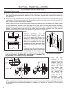
Figure 37: EG40 BV Wiring Diagram.
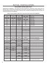
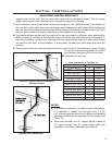
Table 6. Recommended Thermostat Wire
Size.
Wire Size Max. Length
14 gauge 100 ft (30.48 m)
16 gauge 60 ft (18.29 m)
18 gauge 40 ft (12.00 m)
20 gauge 25 ft (7.62 m)
22 gauge 18 ft (5.49 m)
C
O
O
L
/
H
E
A
T
P
R
O
G
R
A
M
D
O
W
N
U
P
7
0
°
F
7
0
°
F
O
N
O
F
F
Figure 38: Wiring of a Thermostat
Initial Installation
QUALIFIED INSTALLERS ONLY