


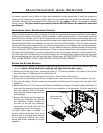
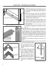
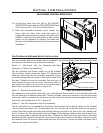

Figure 19: Surround Panel installation.
15
Initial Installation
QUALIFIED INSTALLERS ONLY
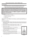
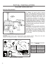
The standard surround panel comes with a fan controller and burner switch so the set that comes with
the unit panel can be kept as spare parts. The fan controller comes pre-mounted in the surround panel
and burner switch is pressed into a notch in the trim. Route the wiring harness through the hole in the
side of the unit marked with an “A” in Figure 20.
Option 3 - Cast Iron Faceplate or Bay Door Assembly.
The fan controller is to be installed into the Focus’ control panel but the burner switch can be installed
into the fascia (see Figure 20). To accomplish this, cut one wire tie so that the wires can be properly
routed. Place the orange and white wires through through the hole in the side of the unit, marked with
an “A” in Figure 20, then along behind the front edge of the replace bottom to the control panel. Use
the wire ties provide to bundle and secure wire. Remove the knob and screw from the fan controller
and place the fan controller through the round hole in the control panel from the back. Tighten nut onto
fan controller from the front of control panel and push on the knob. The burner switch is pressed into a
notch on the edge of the fascia.
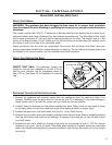
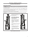
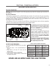
Fan controller location
Wiring harness
Burner switch location
A
Figure 20: Component placement.
Option 1 - Unit Panel, Cast Iron Faceplate, Bay Door
Assembly, or Custom Surround Panel.
The fan controller and burner switch are to be installed
into the Focus’ control panel (see Figure 20). Remove the
knob and screw from the fan controller and place the fan
controller through the round hole in the control panel from
the back. Tighten nut onto fan controller from the front of
control panel and push on the knob. The burner switch is
just pushed into place from the front of the control panel.
Route the wiring harness as shown in Figure 20.
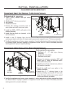
Option 2 - Standard Surround Panel.
FAN CONTROLLER & BURNER SWITCH INSTALLATION:
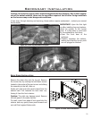
The fan controller and burner switch may be installed in one of three places. Keep the wires away from
the bottom of the rebox or any other hot surfaces.
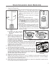
10. Connect the wires from the unit to the ON/OFF/
THERMOSTAT switch and the FAN CONTROLLER (see
INITIAL INSTALLATION - ELECTRICAL REQUIREMENTS).
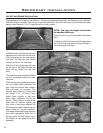
11. Place the assembled surround panel around the
stove, align the slots. Push back then down to
engage the surround panel hooks with the slots in the
replace. Install the decorative fascia or bay window
options to the appliance by aligning the hooks and
the slots in the replace as seen in the surround panel
installation.