


12
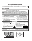
Initial Installation
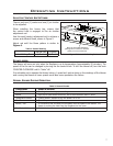
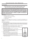
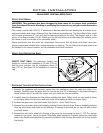
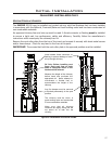
Check draft
with a match
or smoke in
a " (6 mm)
tube located
here.
Warning: Failure to position the parts in accordance with this manual, or failure to use only parts
specically approved with this appliance may result in property damage or personal injury.
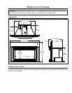
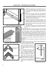
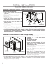
CLEARANCES TO COMBUSTIBLES:
Mantle pillar to glass door 9” (22.8 cm)
From oor to 8” wide mantle 38” (96.5 cm)
Minimum non-combustible surface in front of unit 11” (27.9 cm)
Warning: Clearances must be sufcient to allow access for operation, maintenance and service. Stove
must sit on a non-combustible surface.
Depth of unit into replace 16” (41 cm)
Depth of unit out of replace 3’’ (7.6 cm)
Minimum replace size: Width 34” (86.36 cm)
Height 21” (53.3 cm)
Depth 18” (45.7 cm)
B VENT MODEL:
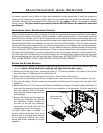
WARNING: This appliance has been designed to operate by drawing combustion air and dilution air
from the room. It is also designed to draw room air for proper heat circulation from the sides of the
unit. Blocking or modifying the louvers in any way can create hazardous situations, either through poor
venting or by overheating. It is important that this unit has sufcient air circulation for proper venting
and combustion. Provisions must be made for the supply of adequate combustion and ventilation air.
These openings must not be blocked. The appliance must not be connected to a chimney ue servicing
a separate solid fuel burning appliance.
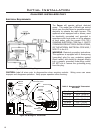
AUTOMATIC FLUE GAS SPILL SWITCH:
NOTE: This heater must be properly connected to a venting system. This heater is equipped with a vent
safety shutoff system designed to protect against improper venting of combustion products. This safety
switch is located on the rear of the appliance close to the draft hood relief opening. If the switch trips
more than once, the venting should be inspected by a qualied service technician for possible blockage
or severe down draft conditions.
BV Only: The draft hood must be in the same pressure zone as the air inlet. To inspect draft from
WARNING: Operation of this heater when not connected to a properly installed and maintained
venting system can result in carbon monoxide (CO) poisoning and possible death.
the front of the unit, locate the ” tube between
the louvers (see Figure 13) and check for a draft
using smoke. A vacuum or suction into the tube will
indicate proper drafting.
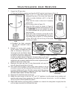
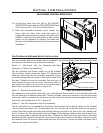
This model can be vented with 4” aluminum or
stainless steel ex vent and/or certied Type B Gas
Vent. The ue collar of the appliance will t inside
of a standard 4” vent and may be fastened directly
to the vent, check periodically that the vent is
unrestricted and an adequate draft is present when
the unit is in operation.
Figure 13: Draft Check.