


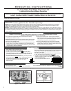
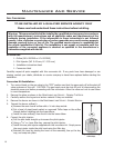

PREPARING YOUR FOCUS FOR INSTALLATION:
1. Remove the appliance and surround panels from the packaging; check to make sure there is no
damage. Carefully check the glass door. Do not use the unit if it is damaged. In the event damage is
found, please report it to both the courier and your dealer as soon as possible.
2. Carefully clean the replace and ue before installing the stove. Failure to do so may result in fumes
or dirt being blown into the room and may cause a re leading to death or serious injury.
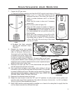
3. Remove the glass door; see MAINTENANCE AND SERVICE - GLASS DOOR REMOVAL.
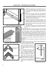
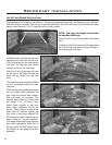
4. Remove log and ember set and all wrapping material from inside the stove. Remove wrapping material
from log and embers and check for any damage. If damage is observed, do not use unit and contact
your local dealer.
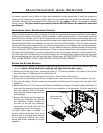
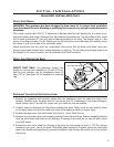
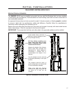
5. Remove the vent collar plate from the top of the stove by unscrewing the two (2) T-20 Torx screws
located on the center top of the stove. Slide collar plate backwards. Properly secure the vent collar
plate to the exible vent pipe liner(s) previously installed in the chimney. Be careful not to over-stretch
the liner(s).
Initial Installation
QUALIFIED INSTALLERS ONLY
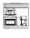
DIRECT VENT MODEL:
WARNING: This appliance has been designed to draw room air for proper heat circulation
from the sides of the unit. Blocking or modifying the louvers in any way can create hazardous
situations.
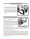
This model is vented with TWO (2) 3” aluminum or stainless steel ex vent leading into a co-linear to co-
axial vent adaptor and using a Simpson Dura Vent vertical termination cap. The ue collars of this model
will t inside of standard 3” vent and may be fastened directly to the vent. The Exhaust vent is in the
center of the ue connector. The Air Intake is on the left side of the vent collar plate (this outlet is not in
the center it is off to one side of the vent collar plate.)
Check periodically that the vents are unrestricted. Also ensure that all direct vent pipes have been
properly sealed and installed after routine inspection or cleaning. The air intake and exhaust pipes must
be installed in the correct locations on the removable draft hood connector.
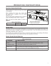
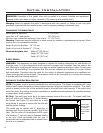
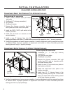
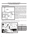
DIRECT VENT RESTRICTOR RING:
Figure 14: Direct vent restrictor ring installation.
Vent Restrictor Ring
DIRECT VENT ONLY: The maximum vertical vent
height for a direct vent installation is 25 feet (7.62 m).
Use the vent restrictor ring for installations above 15
feet (4.57 m). See Figure 14 for installation of restrictor
ring.
13