


23552-1-0607Page 32
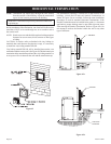
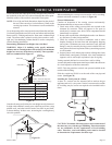
NOTE: When installing this vent system in a chase, it is always
good building practice to insulate the chase as you would the
outside walls of your home. This is especially important for cold
climate installations. Upon completion of building your chase
framing, install the vent system by following the instructions in
this manual. Remember to build the chase large enough so that
minimum clearance of combustible materials (including insulation)
to the vent system are maintained.
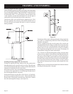
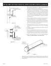
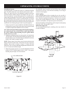
Installation of Vertical Inlet Baffle
The vertical inlet baffle is to be used only in a completely vertical
vent installation. The vertical inlet baffle can be used when the
vertical vent rise is between 10 feet and 40 feet. To maintain the
yellow flame in the main burner, purchase Vertical Inlet baffle,
VIB6A for use with 6 5/8" dia. vent system, or the VIB7A for use
with 7" dia. vent systems. These are available from your Empire
Comfort Systems, Inc. distributor or dealer for Simpson Duravent
only.
In a vertical vent rise the rear (yellow) flame on the main burner can
be reduced due to the drawing action from the flue exhaust pipe and
the air inlet pipe. A decrease in the height or the appearance of the
yellow flame may occur when the vertical vent rise is between 10
feet and 40 feet. To enhance the yellow flame on the main burner,
the vertical inlet baffle can be attached to the Simpson Dura-Vent,
991, direct vent high wind vertical top.
Please refer to the instructions included with the Air Inlet Baffle
Kit for proper installation.
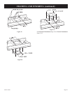
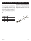
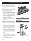
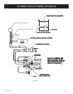
Reassembly and Resealing Vent Pipe System
Attach vent pipe to inlet and outlet vent adaptor on fireplace in either
the vertical or horizontal position, replace horizontal and vertical
pipe lengths, elbows and horizontal or vertical termination kit.
All vent system components lock into place by sliding the concentric
pipe section with four (4) equally spaced interior beads onto the
appliance collar or previously installed component end with four
(4) equally spaced indented sections. When the internal beads of
each starting outer pipe line up, rotate pipe section clockwise 90°
(approximately 3 inches). The vent pipe is now locked together.
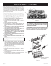
Continue replacing components per the vent system configuration.
Be certain that each succeeding vent component is securely fitted
and locked into the preceding component in the vent system.
Reassembly and Resealing Gas Accumulation Relief System
Glass Frame Assembly and Combustion Chamber
Whenever the glass frame assembly is pivoted open by a delayed
ignition in the main burner, the glass frame assembly gaskets and
combustion chamber must be examined by a qualified service person
for damage. All damaged gaskets on the glass frame assembly and
combustion chamber must be replaced by a qualified service person.
If damage occurs to the combustion chamber, it must be replaced
by a qualified service person. Contact Empire Comfort Systems,
Inc. for replacement parts.
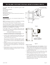
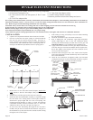
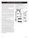
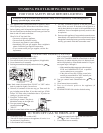
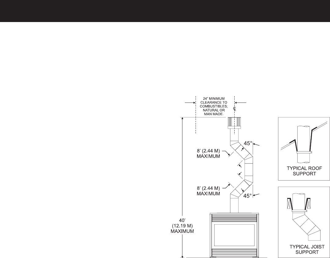
Vertical Through the Roof Applications (Figure 50)
Your Gas Fireplace has been approved for:
a) Vertical installations up to 40 feet in height.
b) Two sets of 45 degree elbow offsets within these vertical
installations. From 0 to a maximum of 8 ft. a vent pipe can be
used between elbows.
c) Wall straps must be used to support offset pipe every 4'.
This application will require that you first determine the roof pitch
and use the appropriate venting components.
Figure 50
VERTICAL TERMINATION (continued)