


23552-1-0607 Page 27
CAUTION: Sharp edges, use protective gloves when
installing.
Tools Needed for Installation:
Sheet metal snips
5/16” nut driver
Phillips head screwdriver - #2
High temperature sealant or furnace cement rated for continuous use
at 1,000
o
F minimum
Measuring tape
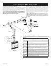
Parts Verification
See parts list on page 29 to verify components included in this vent
kit prior to installation.
NOTE: If installing onto wood, lap, or vinyl siding, the vinyl siding
kit should be used (sold separately, part number DV-822).
The vinyl siding vent kit, DV-822, is available from Empire Comfort
Systems, Inc. The depth is 3” (76mm), which enables the vent cap to
be extended away from vinyl siding or projections. The wall depth plus
the additional 3” (76mm) depth of the vinyl siding vent cap extension
should not exceed a total depth of 13 3/4” (349mm).
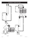
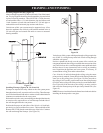
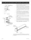
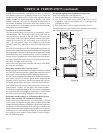
If wall depth exceeds 13 3/4” (349mm), extend system using
6 5/8” (168mm) x 4” (102mm) rigid venting (See Fireplace Instructions
for approved lengths) See Figure 2.
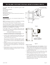
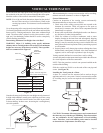
Installing Wall Thimble/Firestop Assembly
1. Fix fireplace to permanent location. If using rigid venting system,
install up to the location where it will exit the building.
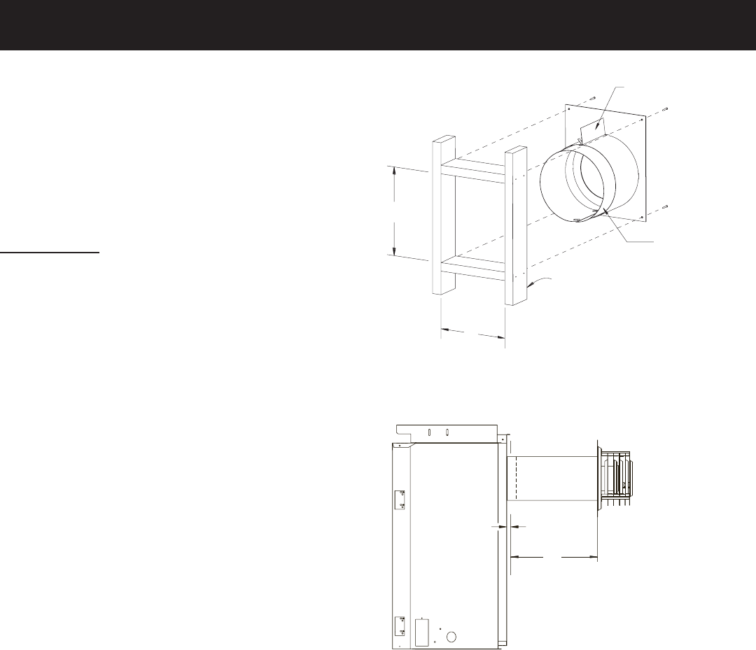
2. Cut hole in wall for wall thimble/firestop assembly (Figure 1) into
your combustible wall. Note: On brick or block exterior wall a 7”
(178mm) diameter hole needs to be cut.
Measure the total wall thickness to determine whether or not the
extension thimble is to be used. If the combustible wall depth is
over 5 3/8” (137mm), then the extension thimble should be used
(Figure 1).
3. Install the wall thimble assembly through the framed opening so the
firestop plate is on the interior wall (Figure 1). Telescope section
should extend all the way through the exterior wall. Attach with
(4) 10 x 1” screws.
4. When placing the vent cap on an exterior wall covered with com
-
bustibles such as wood, lap, or vinyl siding, install the vinyl siding
kit to the exterior wall sheathing.
Figure 1
Figure 2
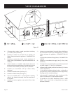
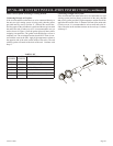
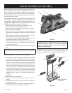
Cutting Vent Tubes
This is the most important part of the installation. With the
fireplace (and the rigid venting system if used) fixed to its perma
-
nent location, the 6 5/8” (168mm) diameter air inlet tube and the
4” (102mm) diameter flue outlet tube are to be marked and cut
using the following procedure.
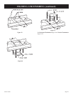
5. Attach the inlet tube to the outside mounting plate. Align
tinnerman clips on the tabs of the air inlet tube to the holes on
outside mounting plate, and fix with (2) #10 x 1/2” screws.
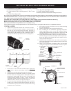
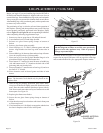
6. With the vinyl siding kit installed to wall (if necessary), insert the 6
5/8” (168mm) diameter tube with outside mounting plate attached
through hole in wall. Connect to collar on fireplace or rigid vent
system. Measure between wall or vent cap extension and outside
mounting plate (Figures 3A and 3B).
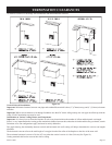
X
X = 13/3/4” MAX
TOTAL W
ALL THICKNESS
(SUBTRACT 3”
IF USING THE
DV822 VINYL SIDING KIT)
½” AIR
SP
ACE
CLEARANCE
11”
9”
NOTE: SPACING FLANGE
INSTALLED TO
TOPSIDE
INTERIOR WALL
EXTENSION
THIMBLE
DVVK-4RE VENT KIT INSTALLATION INSTRUCTIONS