


23552-1-0607 Page 17
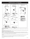
MINIMUM HOLE LOCATION DIMENSIONS FOR THROUGH THE
WALL HORIZONTAL INSTALLATIONS WITH 90 DEGREE ELBOW
OFF TOP OF FIREPLACE
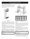
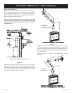
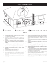
Positioning the Fireplace
Determine the exact position of the appliance so the direct vent termination
will be centered (if possible) between two (2) studs. This will avoid any
extra framing. All vent kit pipes should be assembled on the unit after the
unit is moved into the final position.
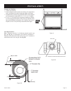
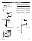
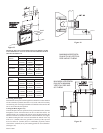
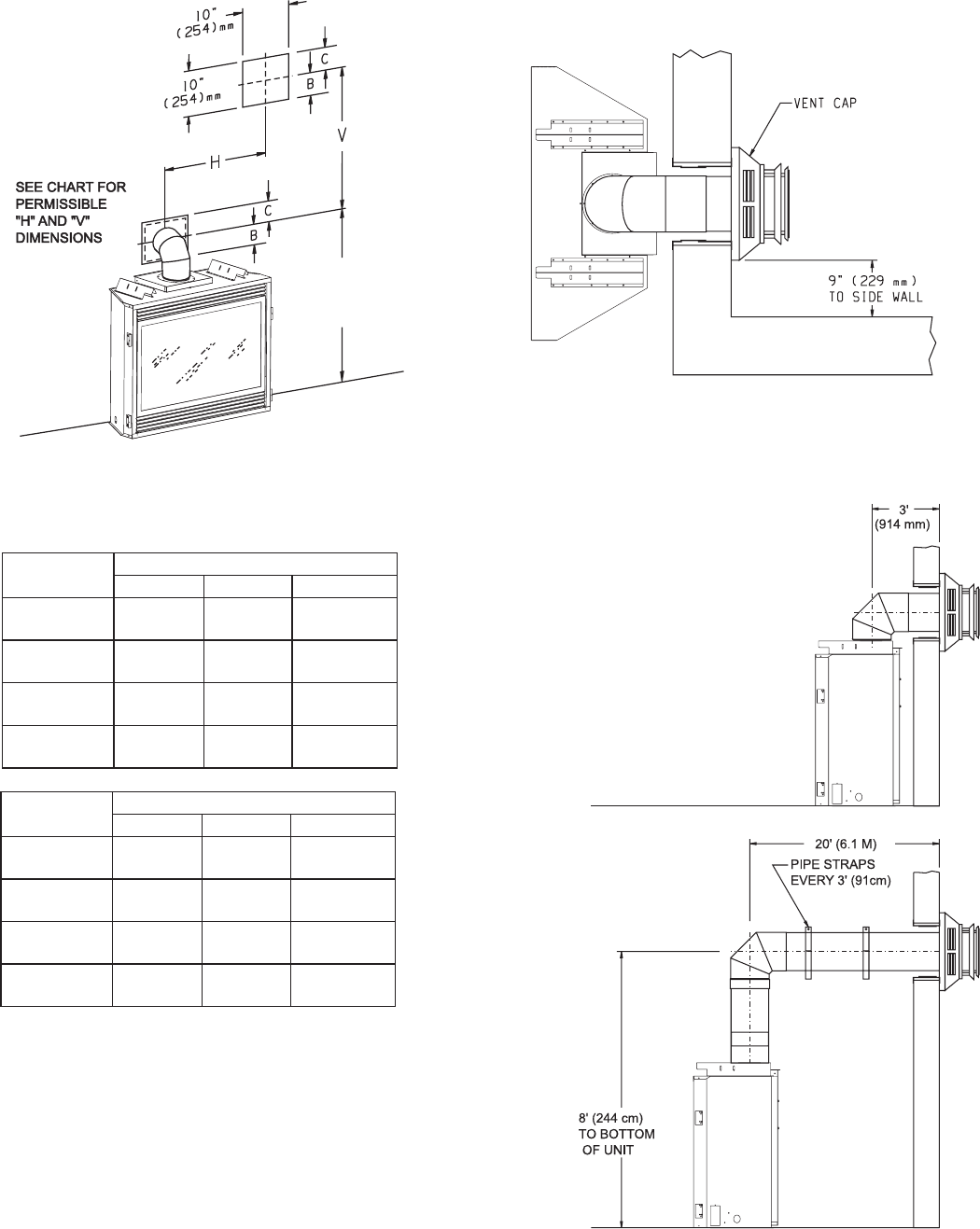
Cutting the Hole (Figures 23)
After the fireplace has been positioned in its permanent location, the hole
through the exterior wall of the house can be cut. This hole must be 10"
(254mm) high x 10" (254mm) wide with its center line determined by the
amount of vertical rise and horizontal run of the termination. (See Figure
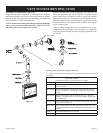
23) When locating the hole it must be noted that the bottom of the cap
must be 12" (305mm) above the ground level, and top of the cap must
be no less than 18" (457mm) below a combustible projection, and no
closer than 9" (229mm) to any wall running parallel to vent termination.
(See Figure 24)
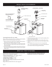
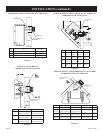
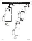
A
CENTER
OF
ELBOW
STRAIGHT
OUT
(MINIMUM)
MAXIMUM HORIZONTAL
RUN WITH NO VERTICAL
RISE AND 90° ELBOW
MAXIMUM HORIZONTAL
RUN WITH MINIMUM
VERTICAL RISE AND
90° ELBOW
minimum
Figure 24
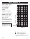
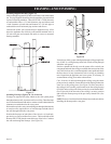
Figure 25
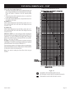
FIREPLACE
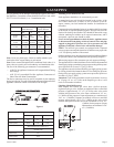
SERIES
HARD ELBOW DIMENSIONS
"A" "B" "C"
DVD32FP 41-1/2"
(1054mm)
4"
(102mm)
6" (152mm)
DVD36FP 41-1/2"
(1054mm)
4"
(102mm)
6"
(152mm)
DVD42FP 43-1/2"
(1105mm)
4"
(102mm)
6"
(152mm)
DVD48FP 43-1/2"
(1105mm)
4"
(102mm)
6"
(152mm)
FIREPLACE
SERIES
FLEX PIPE 90 DEGREE BEND
"A" "B" "C"
DVD32FP 43"
(1092mm)
4-1/2"
(114mm)
6-1/2"
(165mm)
DVD36FP 43"
(1092mm)
4-1/2"
(114mm)
6-1/2"
(165mm)
DVD42FP 45"
(1143mm)
4-1/2"
(114mm)
6-1/2"
(165mm)
DVD48FP 45"
(1143mm)
4-1/2"
(114mm)
6-1/2"
(165mm)
Figure 23