


23552-1-0607Page 30
INSTALLATION
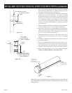
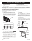
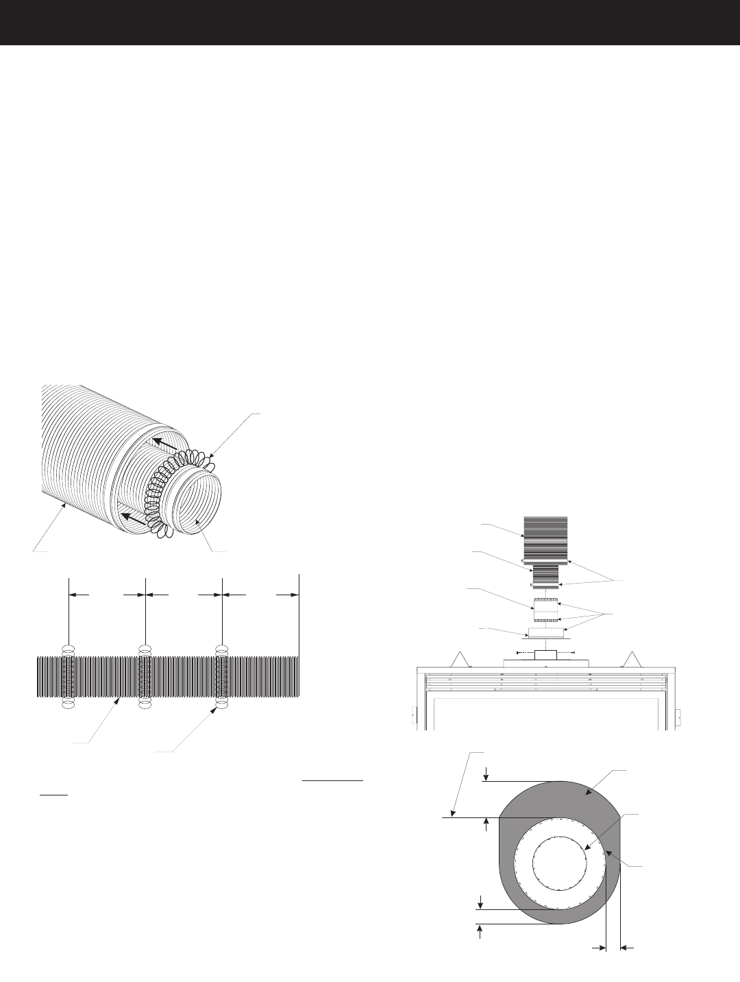
1. Unpack vent components and check that all items are included.
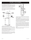
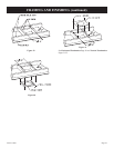
2. Check to see that the vent spacer springs are located around the
flue vent at 8" and 12" intervals along its length. See Figure A.
If not, stretch the spacer springs to about 15" long and wrap them
around the flue, then interlock the ends of each spring about 2".
See Figure B. Maintain equal distance between spring spacers.
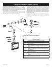
3. Remove the 6-⅝" dia. Vent collar from the fireplace. Replace this
collar with the 7" dia. Flex Vent adapter collar provided with the
vent kit.
4. Slide the Flex Vent flue pipe into the Outer Flex Vent pipe.
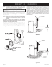
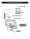
5. Install the Wall Firestop/Thimble assembly as required through
the wall. Refer to the venting charts in the fireplace manual to
determine the proper height and size of the vent opening. The
minimum opening should be 9" wide by 11" high. The minimum
combustible clearance from the horizontal vent is 1" from sides
and bottom, and 3" above the vent pipe. See Figure D.
6. In most cases, after determining the length of the vent that is
needed, it may be easier to install the flue and outer vent pipes to
the Termination Cap first, then from the outside, feed the venting
through the wall to the fireplace.
7. If the venting is to long, trim off any excess vent before attaching
the vent end connectors.
8. Attach the Termination Cap to the outside of the house.
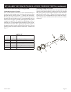
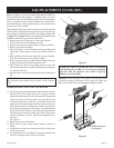
9. Prior to making the vent connections, apply high temperature
sealant (1000 degree F min.) to the vent connections before
securing with the band clamps provided. Note: the flue pipe end
without the adapter is to be installed to the Termination Cap.
10. Apply sealant to the outside of the flue pipe adapter and connect
to the flex flue pipe. Then insert the adapter into the fireplace flue.
Secure flue adapter to the fireplace flue with a minimum of two
screws provided. See Figure C.
11. Attach the Outer Vent pipe to the 7" dia. Collar on the fireplace
with a large band clamp provided. Sealant may also be used on the
outer vent connections.
12. Check all vent connections for tightness. Make sure horizontal
venting has the proper rise and combustible clearances required.
Refer to venting charts in fireplace instruction manual.
8
(203 mm)
8
(203 mm)
8
(203 mm)
4 FLEX
VENT PIPE
SPACER
SPRING
FIGURE B
””
”
”
”
FLEX OUTER VENT FLEX FLUE PIPE
SPACER
SPRING
S
FIGURE A
Top of Vent
Combustibles NOT
allowed in shaded
area
1"
1"
3"
(25
mm)
7
” Diameter
intake vent
4” Diameter flue
(25 mm)
(76 mm)
FIGURE D
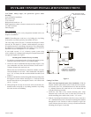
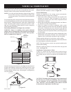
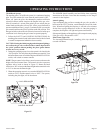
Flex venting can be installed either vertically or horizontally off of the DVD Series fireplaces. When installing a horizontal vent run from top
connections, maintain at least ½" rise for every 12" of vent run. When venting horizontal off the rear vent connections, allow a minimum rise
of 2". Refer to Figure 42 when mounting termination near vinyl siding.
CAUTION: Always stretch and secure venting with wire or metal strapping to ensure that the horizontal runs do not sag.
If space permits, it is generally easier to attach venting in the top vent configuration.
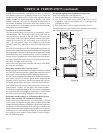
Because of sharp edges, always use gloves when handling the flex vent components.
Vent connections should overlap a minimum of 1" for proper sealing.
Always follow the general venting requirements for vent terminal location, vent lengths, and clearance to combustible materials.
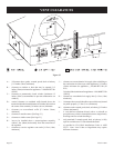
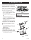
The DVVK-4F FLEX VENT KIT includes the following components:
• (1) Horizontal Termination Cap
• (1) 4-foot section of Flex vent with spacers (4" flue/7" outer
pipe)
• (1) 4" dia. Flue adapter collar
• (1) 7" dia. Outer Vent adapter collar
• (1) Wall Firestop/Thimble Assembly
• Hardware pack that includes band clamps and screws
BAND CLAMP
4 DIA. FLUE
ADAPTOR
COLLAR
4 DIA. FLEX
FLUE PIPE
7 DIA. FLEX
VENT PIPE
APPLY HIGH
TEMPERATURE
SEALANT
7 DIA. INLET
ADAPTOR COLLAR
(WITH GASKET)
FIGURE C
”
”
”
”
DVVK-4F FLEX VENT INSTRUCTIONS