


23552-1-0607 Page 31
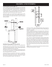
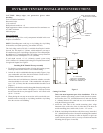
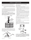
Locate and mark the center point of the vent pipe using a nail on
the underside of the roof. Drive the nail through the center point.
Mark the outline of the roof hole around this center point.
NOTE: Size of the roof hole dimensions depend on the pitch of
the roof. There must be a 1 inch clearance (25mm) to the
vertical pipe sections. This clearance is to all combustible
material.
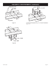
Cover the opening of the vent pipe and cut and frame the roof hole.
Use framing lumber the same size as the roof rafters and install the
frame securely. Flashing anchored to frame must withstand high
winds. The storm collar is placed over this joint to make a water-
tight seal. Non-hardening sealant should be used to completely
seal this flashing installation.
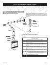
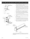
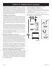
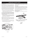
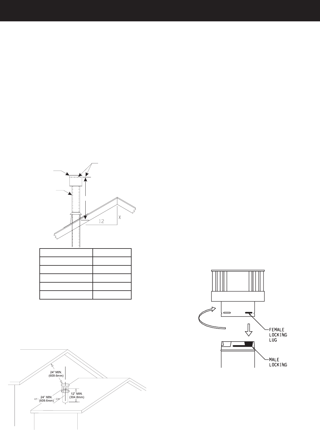
Determining Minimum Vent Height Above the Roof.
WARNING: Major U.S. building codes specify minimum
chimney and/or vent height above the roof top. These minimum
heights are necessary in the interest of safety. These specifica
-
tions are summarized in Figure 47.
Figure 47
Note that for steep roof pitches, the vent height must be increased.
In high wind conditions, nearby trees, adjoining roof lines, steep
pitched roofs, and other similar factors can result in poor draft,
or down-drafting. In these cases, increasing the vent height may
solve this problem.
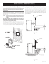
When terminating the vent cap near an exterior wall or overhang,
maintain minimum clearances as shown in Figure 48.
General Maintenance
Conduct an inspection of the venting system semi-annually.
Recommended areas to inspect are as follows:
1. Check areas of the venting system which are exposed to the
elements for corrosion. These will appear as rust spots or
streaks and, in extreme cases, holes. These components should
immediately be replaced.
2. Remove the cap and shine a flashlight down the vent. Remove
any bird nests or other foreign material.
3. Check for evidence of excessive condensate, such as water
droplets forming in the inner liner and subsequently dripping
out at joints. Condensate can cause corrosion of caps, pipe and
fittings. It may be caused by having excessive lateral runs, too
many elbows and exterior portions of the system being exposed
to cold weather.
4. Inspect joints to verify that no pipe sections or fittings have been
disturbed and, consequently, loosened. Also, check mechanical
supports, such as wall straps or plumbers’ tape for rigidity.
Venting terminal shall not be recessed into a wall or siding.
A removable panel or other means must be provided in the enclosure
for visual inspection of the flue connection.
NOTE: This also pertains to vertical vent systems installed on the
outside of the building.
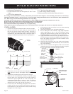
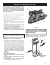
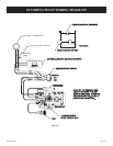
Slide the vertical top SD-991 over the ends of the vent pipe and
secure. (See Figure 49)
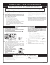
Installing the Vent System in a Chase
A chase is a vertical box-like structure built to enclose the gas
appliance and/or it’s vent system. Vertical vent runs on the outside
of a building may be, but are not required to be installed inside a
chase.
Figure 49
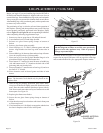
CAUTION: Treatment of firestop spacers and construction of
the chase may vary with the type of building. These instructions
are not substitutes for the requirements of local building
codes. Therefore, your local building codes must be checked
to determine the requirements for these steps.
VENT CAP
GAS VENT
H
LOWEST
DISCHARGE
OPENING
H (Min.) - Minimum height from
roof
to lowest discharge opening
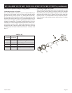
ROOF PITCH
IS X/12
ROOF PITCH H (Min.)
Flat to 6/12 12" (305 mm)
6/12 to 7/12 15" (381 mm)
Over 7/12 to 8/12 18" (457 mm)
Over 8/12 to 16/12 24" (610 mm)
Over 16/12 to 21/12 36" (914 mm)
VERTICAL TERMINATION
Figure 58