


□
Make sure that the process gas meets the recommended characteristics regarding
composition, temperature, and pressure for your installation.
□
Verify that you have all equipment necessary for your installation. Depending on
your application, you may be required to install additional parts for optimal
performance of the meter.
□
Follow recommended best practices for installing the GDM to account for the
effects of density, temperature, and pressure equilibrium.
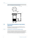
1.2 Best practices
The following information can help you get the most from your meter.
• Handle the meter with care. Follow local practices for lifting or moving the meter.
• Ensure that the process gas is clean and dry.
• Do not use gases incompatible with the materials of construction. To prevent
corrosion of the sensing element, the process gas should be compatible with
Ni-Span-C.
• Do not expose the meter to excessive vibration (greater than 0.5 g continuously).
Vibration levels in excess of 0.5 g can affect the meter accuracy.
• Perform a Known Density Verification (KDV) check of the meter prior to installing
the meter in your system.
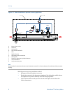
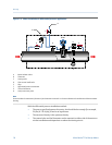
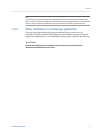
• Installing the meter in a bypass configuration allows you to remove the meter for
servicing or calibration without affecting the main pipeline.
• Install the meter in a thermo-well pocket to ensure the temperature of the sample
gas is equal to that of the pipeline gas. Micro Motion thermo-well pocket kits are
available for purchase.
• Minimize the length and volume of the input sample pipe to ensure an optimal
meter response time. Use 6 mm (1/4 in) instrument tubing and low-volume inlet
filters.
• Control gas flow with a needle valve mounted before or after the meter, depending
on the installation.
• Install an external coalescing filter in the sample gas inlet pipework to minimize
condensate and dust contamination.
• Verify that the filters in your system are not causing any excessive flow restrictions.
• Verify that the pressure of the process gas is approximately equal to the pipeline
pressure.
• Do not exceed more than a 10% reduction of the cross-sectional area at the point of
insertion in the pipeline to ensure minimal effect on pressure.
• Ensure that the meter and associated pipework are pressure-tested to 1½ times the
maximum operating pressure after installation.
• Install thermal insulation to the meter and the inlet and bypass-loop pipeline to
maintain temperature equilibrium between the sample and pipeline gases. Do not
insulate the transmitter (electronics) and maintain a nominal 1-in clearance
between the insulation and the transmitter housing.
Planning
2 Micro Motion
®
Gas Density Meters