


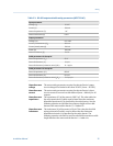
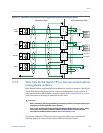
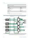

RS-485 output and cable entity parameters (MTL7761AC)Table 3-3:
Input parameters
Voltage (U
i
) 18 VDC
Current (I
i
) 100 mA
Internal capacitance (C
i
) 1 nF
Internal inductance (L
i
) 0.0 H
Output parameters
Voltage (U
o
) 9.51 VDC
Current (instantaneous) (I
o
) 480 mA
Current (steady state) (I) 106 mA
Power (P
o
) 786 mW
Internal resistance (R
i
) 19.8 Ω
Cable parameters for Group IIC
External capacitance (C
o
) 85 nF
External inductance (L
o
) 154 µH
External inductance/resistance ratio (L
o
/R
o
) 31.1 µH/Ω
Cable parameters for Group IIB
External capacitance (C
o
) 660 nF
External inductance (L
o
) 610 µH
External inductance/resistance ratio (L
o
/R
o
) 124.4 µH/Ω
Hazardous area
voltage
The meter entity parameters require the selected barrier’s open-
circuit voltage to be limited to less than 30 VDC (Vmax = 30 VDC).
Hazardous area
current
The meter entity parameters require the selected barrier’s short-
circuit currents to sum to less than 484 mA (Imax = 484 mA) for all
outputs.
Hazardous area
capacitance
The capacitance (Ci) of the meter is 0.0011 μF. This value added to
the wire capacitance (Ccable) must be lower than the maximum
allowable capacitance (Ca) specified by the safety barrier. Use the
following equation to calculate the maximum length of the cable
between the meter and the barrier: Ci + Ccable ≤ Ca
Hazardous area
inductance
The inductance (Li) of the meter is 0.0 μH. This value plus the field
wiring inductance (Lcable), must be lower than the maximum
allowable inductance (La) specified by the safety barrier. The
following equation can then be used to calculate the maximum cable
length between the meter and the barrier: Li + Lcable ≤ La
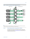
Wiring
Installation Manual 25