


Information provided about wiring the safety barriers and galvanic isolators is intended as
an overview. You should wire the meter according to the standards that are applicable at
your site.
CAUTION!
• Meter installation and wiring should be performed by suitably trained personnel only in
accordance with the applicable code of practice.
• Refer to the hazardous area approvals documentation shipped with your meter. Safety
instructions are available on the Micro Motion Product Documentation DVD and
accessible on the Micro Motion website at www.micromotion.com.
3.2.1 Hazardous area entity parameters
DANGER!
Hazardous voltage can cause severe injury or death. To reduce the risk of hazardous voltage,
shut off power before wiring the meter.
DANGER!
Improper wiring in a hazardous environment can cause an explosion. Install the meter only in
an area that complies with the hazardous classification tag on the meter.
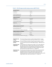
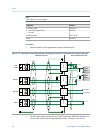
Input entity parameters
Input entity parameters: all connectionsTable 3-2:
Parameter Power supply
4–20 mA /Discrete
Output/Time Period
Signal RS-485
Voltage (U
i
) 30 VDC 30 VDC 18 VDC
Current (I
i
) 484 mA 484 mA 484 mA
Power (P
i
) 2.05 W 2.05 W 2.05 W
Internal capacitance
(C
i
)
0.0 pF 0.0 pF 0.0011 pF
Internal inductance (L
i
) 0.0 H 0.0 H 0.0 H
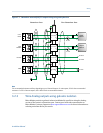
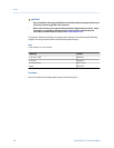
RS-485 output and cable parameters
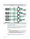
All connections to the meter receive their power from the connected intrinsically safe
barrier. All cable parameters are derived from the output parameters of these devices. The
RS-485 connection also receives power from the connected barrier (MTL7761AC),
although this connection has specific output and cable parameters.
Wiring
24 Micro Motion
®
Gas Density Meters