


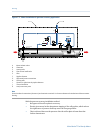
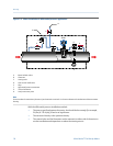
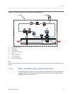
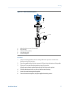

Meter installation in an ultrasonic meter applicationFigure 1-8:
STATUS
SCROLL SELECT
E
C
A
B
D
A
G
H
F
GDM
A. Meter isolation valves
B. Flowmeter
C. Venting valve
D. Flow control needle valve
E. Filter
F. Annubar flowmeter
G. Thermal insulation
H. Vent/vacuum test point
Note
Do not insulate the transmitter (electronics) and maintain a nominal 1-in clearance between the insulation and the transmitter
housing.
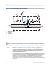
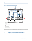
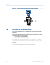
1.6.4 Meter installation with a turbine flow meter
The following diagram shows a meter measurement system with a gas turbine flowmeter
installation. Refer to manufacturer guidelines for best practices or recommendations for
installing the meter in your system.
Planning
Installation Manual 13