


If the LCD pins are inadvertently removed from the interface board, carefully re-
insert the pins before snapping the LCD in place.
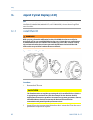
After installation, you can remove the LCD by squeezing the two tabs and pulling
gently. You can then rotate it in 90-degree increments and snap it back in place.
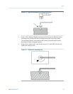
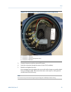
3. Attach the LCD cover.
Use a strapping wrench to tighten the cover until it will no longer turn and the black
O-ring is no longer visible.
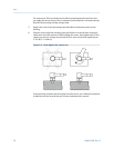
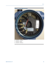
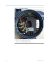
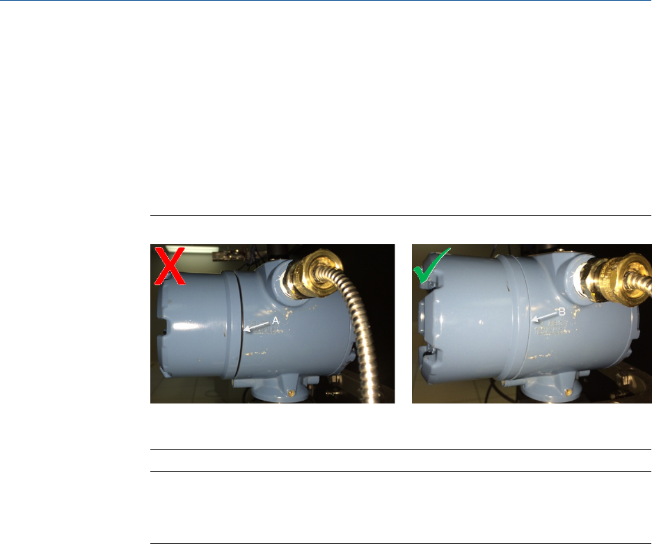
Sealing the end capFigure 3-12:
A. Improperly sealed end cap. Black O-ring is still visible.
B. Properly sealed end cap. Black O-ring is no longer visible.
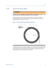
Important
Moving one LCD around to multiple devices, on an “as need” basis, is NOT recommended.
This can cause reliability problems over time. The connector pins on the LCD are not designed
for repeated connect/disconnect.
3.3.2 Enable the LCD
When you enable the LCD, the CSI 9420 displays information about its network state and
its measurements. This is helpful for configuration, installation, and commissioning. The
LCD provides a visual indication on the status of the device and shows its current
measurements.
Transmitters ordered with the LCD are shipped with the display installed but with the LCD
disabled/turned off. You need to enable the LCD using a Field Communicator or using AMS
Device Manager.
Enable the LCD using a 375 or 475 Field Communicator
1. Use the lead set to connect the Field Communicator to the CSI 9420 terminal block.
2. Turn on the Field Communicator.
3. Select Configure > Manual Setup > General Settings > LCD Mode > Periodic Display.
Options available for LCD configuration include:
• Not installed – Use this setting if the LCD is not installed.
Setup
MHM-97408, Rev 15 83