


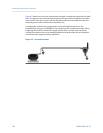
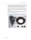

The ferrite in this example is Fair-Rite P/N 0431164281, which has a reactance that ranges
from 28 Ω at 1 MHz to 310 Ω at 100 MHz and 240 Ω at 250 MHz. It supports a maximum
cable diameter of 0.260 inch (6.6 mm).
Effect of ferrites on interference
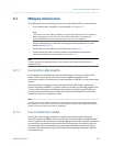
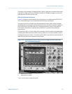
Figure 6-10 compares two accelerometers in the presence of a high-intensity RF field (10
V/m). The oscilloscope is the time-domain representation of the signals.
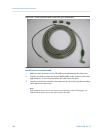
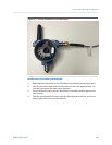
The upper trace (A) is a standard (non-armor-jacketed) 3-meter cable, without conduit,
with polarization matching that of the interference field, and with two ferrites installed at
the accelerometer end of the cable. The resulting interference is about 10 mV peak-to-
peak, which is equivalent to a perturbation of about 0.2 g's peak to the acceleration
measurement.
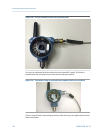
The lower trace (B) is a 3-meter cable of the same type, without conduit, with polarization
matching that of the interference field. In this case there are no ferrites installed, and the
resulting interference is about 1.2 V peak-to-peak, which is equivalent to a perturbation of
about 24 g's peak to the acceleration measurement.
Accelerometer signals in the presence of high-intensity interference
with and without mitigation*
Figure 6-10:
A. With two ferrites installed
B. Without ferrites installed
*Scale is not the same for A and B in this graph.
Accelerometer EMI and RFI considerations
MHM-97408, Rev 15 111