


3 Setup
Topics covered in this chapter:
• Power the CSI 9420
• Sensors
• Liquid Crystal Display (LCD)
• Ground the transmitter
3.1 Power the CSI 9420
Prerequisites
Install the Smart Wireless Gateway and ensure it is functioning properly before installing
the CSI 9420 and all other wireless devices.
Procedure
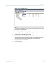
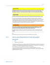
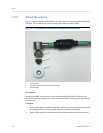
1. Remove the transmitter back cover to access the power connections.
2. Provide power to the transmitter:
• For the battery-powered version, plug in the power module.
• For the externally powered version, connect a 10–28 VDC (24 V nominal) power
supply to the bottom two screw terminals on the right.
Note
When selecting the power supply, note that each CSI 9420 has a peak current draw of 40 mA
when awake and powering sensors.
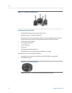
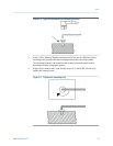
3. Pull the wiring through the threaded conduit entry.
Ensure that the grommet fits the wire properly and does not leak.
Note
The wire must snugly fit in the grommet feed-through in the cable gland to prevent ingress of
water and other contaminants. If using one of the grommets for the standard low-power
accelerometers, use a cable with a diameter between 0.125 to 0.250 in. (3.175 - 6.35 mm) to
maintain a good seal. If a good seal is not possible with the wire selected, use an alternative
grommet that provides a good seal.
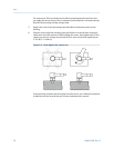
Additional recommendations for power wiring:
• Install a Ferrite EMI filter inline with the wire to block electrical noise (included with
package). Refer to Section 6.1.3 for more information.
• Use 22 gauge or larger wiring (keep current requirements in mind when connecting
multiple transmitters inline).
Setup
MHM-97408, Rev 15 69