


3.2.7 Conduit installation guidelines
WARNING!
All wiring should be installed by a trained and qualified electrician. Wiring must conform to all
applicable local codes and regulations.
• Adhere to IEEE 1100 specifications for grounding.
• Do not exceed a 40 percent fill for conduits.
• Route the conduit away from power trays using these guidelines:
6 in. 110 VAC
12 in. 220 VAC
24 in. 440 VAC
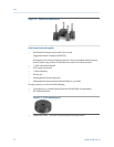
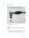
• Attach the conduit to the NPT threaded holes on the side of the CSI 9420.
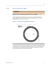
3.2.8 Connect the sensors
WARNING!
If the sensor is installed in a high-voltage environment and a fault condition or installation
error occurs, the sensor leads and transmitter terminals could carry lethal voltages. Use
extreme caution when making contact with the leads and terminals.
Procedure
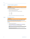
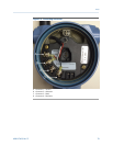
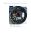
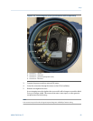
1. Remove the transmitter back cover.
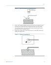
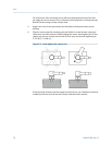
2. Attach the sensor leads. Follow the wiring diagram in Figure 3-8 to connect one
sensor, the wiring diagram in Figure 3-9 to connect two sensors, and the wiring
diagram in Figure 3-10 to connect one sensor with temperature.
Note
You can connect one or two accelerometers to the CSI 9420. You can connect only one
accelerometer with a temperature sensor.
Setup
78 MHM-97408, Rev 15