Operation
13
5.4 Unit Controls
5.4.1 Remote Control Interface
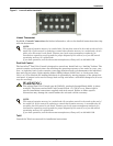
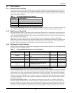
Control connections to the InteleCool2 unit use customary HVAC terminal designations R, G, W & Y.
Contact closures between the 24 VAC (R) and different control connections supply control voltage to
the electric panel components responsible for the desired function. Operating modes are controlled by
contact closures as follows:
Wall-mounted thermostats are to be low voltage, snap action or mercury type. Un-manned sites should
use a HEAT/COOL/AUTO type subbase to provide automatic switchover during climate changes.
5.4.2 High Pressure (Standard)
The high pressure switch is mounted in the liquid line. Electrically, it is connected in series with the
compressor start circuit, which will shut down the compressor and condenser fan if the liquid pres-
sure exceeds 400 PSIG (2758 kPa). This protects the InteleCool2 in the event of condenser motor fail-
ure or condenser coil blockage.
The pressure switch is an auto reset device. When the system pressure drops below 300 PSIG
(2069 kPa), the switch will reset. (An optional lockout relay is available which allows the switch to be
used as a manual reset safety.) If the call for cooling is present, the compressor start circuit will be
energized and the compressor will start after the 3 minute anti-short cycle time.
5.4.3 Refrigeration Control Options
Please review the following table for the recommended control options based on the site ambient and
your need for year-round operation.
Low Pressure Switch and Low Pressure Bypass Timer (Winter Start)
Low Pressure Switch—The low pressure switch is mounted in the compressor suction line. Electri-
cally, it is connected in series with the compressor start circuit, which will shut down the compressor
and condenser fan if the suction pressure drops below 35 PSIG (241 kPa). The switch will automati-
cally reset once the system pressure rises above its cut-in setting (60 psig, ±5 psig [414 kPa, ±34 kPa]).
This protects the InteleCool2 in the event the evaporator fan fails, the filter becomes clogged or there
is a loss of refrigerant. If the call for cooling is present, the compressor will start after the 3 minute
anti-short cycle time.
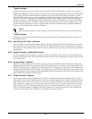
Low Pressure Bypass Timer—A low ambient temperature start relay is included with the low
pressure option. This relay locks out (ignores) the low pressure switch on start-up until the system
pressure stabilizes. This bypass relay is adjustable and should be set for 3 minutes greater than the
anti-short cycle timer setting. This option can be used for applications down to 50°F (10°C). For con-
trol down to -20°F (-28.9°C), use the T-pack1 and T-pack2 options, which include fan cycle control.
Table 2 Operating modes/contact closures
Connection Operating Mode
R 24 VAC
G Evaporator Fan
WHeating
Y Cooling (compressorized or Economizer)
Table 3 Recommended applications for control options
Application Unit Options Min ambient Max ambient
General Standard None 50°F (10°C) 115°F (46.1°C)
General Standard
Low pressure with low pressure bypass
timer
50°F (10°C) 115°F (46.1°C)
General Standard T-pack1 or T-pack2 -20°F (-28.9°C) 115°F (46.1°C)
Telecom/365-day operation Standard T-pack1 or T-pack2 -20°F (-28.9°C) 115°F (46.1°C)
General Standard High ambient 50°F (10°C) 125°F (51.7°C)
General Standard
High ambient, low pressure with low
pressure bypass timer
50°F (10°C) 125°F (51.7°C)
Telecom/365-day operation Standard High ambient with T-pack1 or T-pack2 -20°F (-28.9°C) 125°F (51.7°C)


