


Installation
6
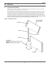
2.4 Ducting
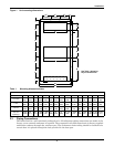
Field-supplied ducting can be attached to the unit duct connection once the unit has been mounted to
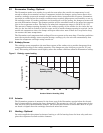
the outside wall. The total external static pressure for the duct, including grille, must not exceed the
values shown in Table 5 and Table 6. Indoor discharge air rates are also given in the same tables.
2.5 Electrical Connections
Each unit is shipped from the factory with all internal wiring completed. Refer to the electrical sche-
matic when making connections. Electrical connections to be made at the installation site are: line
voltage power supply to the power input and control wiring to remote control (customer supplied or
Liebert option). DO NOT RUN CONTROL WIRING WITH HIGH VOLTAGE!
2.5.1 Power Connections
All power and control wiring and ground connections must be in accordance with the National Electri-
cal Code and local codes
Use copper wiring only. Make sure that all connections are tight.
Make sure that the voltage supplied agrees with the voltage specified on the unit nameplate. The
InteleCool2 comes standard with a factory-installed circuit breaker, accessible through an external
access panel. An external, wall-mounted power disconnect switch (field-supplied) may be required for
local codes. If necessary, this switch should be wired according to those codes.
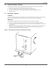
For access to the electrical enclosure:
• Remove the screws securing the middle panel and pull the panel down and forward to remove.
• Remove the screws securing the electric box cover and remove cover.
• Verify that the unit wiring is correct for the actual input power. Some units are built with multi-
voltage serial tags. The transformer may need to be re-tapped if the actual input voltage is differ-
ent (see serial tag and electrical schematic).
Route the supply power to the customer-supplied disconnect switch (if required) and then to the unit
circuit breaker inside the unit. Route the conduit to the hole provided in the cabinet. Connect the
earth ground to the lug provided near the circuit breaker. Refer to the unit wiring diagram supplied
on the inside of the electrical enclosure cover.
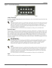
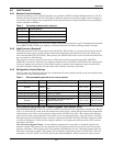
2.5.2 Control Connections
Control wiring will be required for the remote control device. This remote device may be a factory- or
field-supplied wall thermostat or similar device. Connections to the unit are made using customary
HVAC low volt wiring terminals R, G, W, and Y. For detailed locations of the low volt wiring termi-
nals, please refer to the Figure 11 - Electric panels.
!
WARNING
Use voltmeter to make sure power is turned off before making any electrical connections.
!
CAUTION
Refer to electrical schematic when making connections.
!
CAUTION
The optional three-phase scroll compressor must rotate in the correct direction to ensure
proper system operation. Wiring must be phased and connected as shown:
• PHASE “A” to T1 or L1
• PHASE “B” to T2 or L2
• PHASE “C” to T3 or L3