Installation
4
2.0 INSTALLATION
2.1 Preparation
2.1.1 Room Preparation
The room should be well-insulated and should be sealed to reduce airborne contaminants from pene-
trating the site. Outside air may be introduced through the damper option or be used for economized
cooling by using the Economizer option. However, uncontrolled outside air should be kept to a mini-
mum. Outside air adds to the cooling, heating, and filtration loads of the site. Doors should be prop-
erly sealed to minimize leaks and should not contain grilles.
2.1.2 Location Considerations
The InteleCool2 unit is field-mounted on an outside wall. Additional framing in the wall may be
required to ensure adequate structural support.
The outdoor area near the condenser supply and discharge must also be considered. To assure ade-
quate air supply, the unit should be mounted in a clean area, away from loose dirt and foreign matter
that may clog the condenser coil. The unit should not be located near steam, hot air, or fume exhausts.
Also, the unit should not be mounted closer than 12 feet (3.7 m) from an opposing wall, obstruction or
unit. For service clearance, provide 36 inches (914 mm) in front of the unit, and 30 inches (762 mm) on
each side. When mounting units side by side, provide a minimum of 36 inches (914 mm) between adja-
cent units unless the adjacent units will not be run at the same time. In this case, the units may be
placed as close as 18 inches (457 mm) apart. However, this will make the units more difficult to service.
In such situations, consider the compressor location option for improved serviceability. Before mount-
ing units, check local codes for applicable clearances.
2.1.3 Equipment Inspection
Upon delivery of the unit, inspect all items for visible damage. Concealed damage may be discovered
later during installation. Report any damage to the shipper immediately and file a damage claim.
Also, forward a copy of the damage claim to your Liebert supplier.
2.2 Unit Installation
The InteleCool2 unit is installed against, and through, an outside wall. Two (2) openings in the wall
are required for the evaporator supply and return. Provide 1/2" clearance on wall openings for supply
and return air. Install the unit in a level position to assure proper refrigerant flow, oil return, and
condensate drain. To install the unit, follow the instructions below.
1. Verify that an adequate structural support is provided for the unit.
2. Using a chalk line, mark the outside wall with a level horizontal line, where the bottom of the unit
is to rest.
3. Prepare supply and return openings in an outside wall, measuring up from the chalk base line.
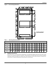
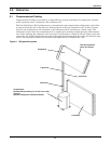
4. Prepare mounting holes. The mounting holes may be pilot holes for lag screws or clearance holes
for bolts that will extend completely through the wall. Refer to Figure 1 for the location of these
holes.
5. Fasten the unit mounting base angle to the outside wall with six 5/16" bolts or lag screws (not
supplied), just below chalk line and centered on the opening in the wall.
6. With the unit front panel removed, lift the unit onto the base angle, making certain that the rear
unit angle falls behind the turned up front edge of the mounting angle. Insert top and side unit
fasteners in holes and tighten, drawing the unit into place. Do not attach ducts to unit prior
to installing unit.
7. Caulk and flash the top and sides as required to form a watertight seal. Top flashing (not factory
supplied) is recommended to ensure that water does not run behind unit. All unit tops are sloped
to allow water to run off.
!
WARNING
Use caution and adequate equipment to safely handle unit. Weight of each unit ranges
from 330 to 490 lbs. (150 to 222 kg), depending on model.


