


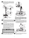
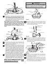
22. Securely connect the wiring harness connector to
the receiver connector, and connect the blue and
yellow wires to the blue and yellow wires from the
receiver (Figure 4).
23. Turn the receiver so that the flat side aligns with
the open side of the hanger bracket (Figure 15).
Fold and position the wires into the space above
the hanger ball and into the outlet box.
24. Feed the wires and connectors around the out-
side of the receiver, through the open side of the
hanger bracket, and into the outlet box. Slide the
receiver up and over the hanger bracket.
Remove the backing on the foam adhesive pads
and press the receiver against the ceiling.
25. To complete the ceiling fan assembly, skip to the
“FINAL ASSEMBLY” section of this Owner’s
Manual.
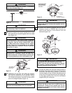
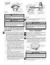
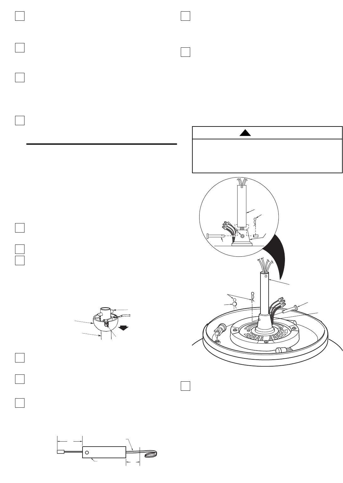
7. Route the white, blue, and black motor leads through
the downrod. Fold the yellow, red, and brown wires
into the slot in the motor coupling, slide the downrod
down the wires and seat the downrod in the motor
coupling (Figure 18).
8. Align the clevis pin holes in the downrod with the
holes in the motor coupling. Install the clevis pin and
secure with the hairpin clip (Figure 18). The clevis pin
must go through the holes in the motor coupling and
the holes in the downrod . Push the straight leg of the
hairpin clip through the hole near the end of the
clevis pin until the curved portion of the hairpin clip
snaps around the clevis pin. The hairpin clip must be
properly installed to prevent the clevis pin from
working loose. Pull on the hanger ball to make sure
the clevis pin is properly installed.
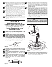
9. Install the setscrew (supplied in loose parts bag) in
the motor coupling and tighten using the 5/32"
setscrew wrench (supplied) (Figure 19).
8
SECTION B
Assembly Instructions for
Installing the CF2500 Ceiling Fan
with Any Other Control Method
(excluding the SW375 Receiver,
SR330 Remote Control or the
SW350 Wall Control)
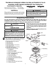
1. Position the fan motor and housing assembly in the
lower foam packing so that the top of the motor is
facing you.
2. Separate, untwist and unkink the four motor leads.
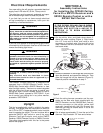
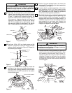
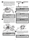
3. Obtain the hanger ball/downrod assembly and
remove the hanger ball by loosening the setscrew
in the hanger ball until the ball falls freely down the
downrod (Figure 16). Remove the pin from the
downrod , then remove the hanger ball. Retain the
pin and hanger ball for reinstallation in step 9.
4. Push the uplight yellow lead assembly connector
through the downrod (Figure 17) until it extends
about 4”.
5. Cut the yellow lead approximately 3” from the end
of the pipe. Strip insulation 1/2” from end of the
wires.
6. Using the wire connector supplied, connect the
uplight yellow lead assembly to the yellow lead
from the fan motor and housing assembly
(Figure 18).
HANGER BALL
DOWNROD
CLEVIS PIN
SETSCREW
Figure 16
4"
DOWNROD
CUT
HERE
3"
UPLIGHT YELLOW
LEAD ASSEMBLY
Figure 17
It is critical that the clevis pin in the motor coupling
is properly installed and the setscrew securely
tightened. Failure to verify that the pin and setscrew
are properly installed could result in the fan falling.
WARNING
!
SETSCREW
CLEVIS PIN
MOTOR
COUPLING
DOWNROD
HAIRPIN
CLIP
MOTOR
COUPLING
HAIRPIN
CLIP
CLEVIS
PIN
DOWNROD
CLEVIS
PIN
Figure 18