


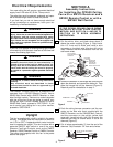
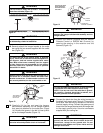
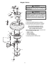
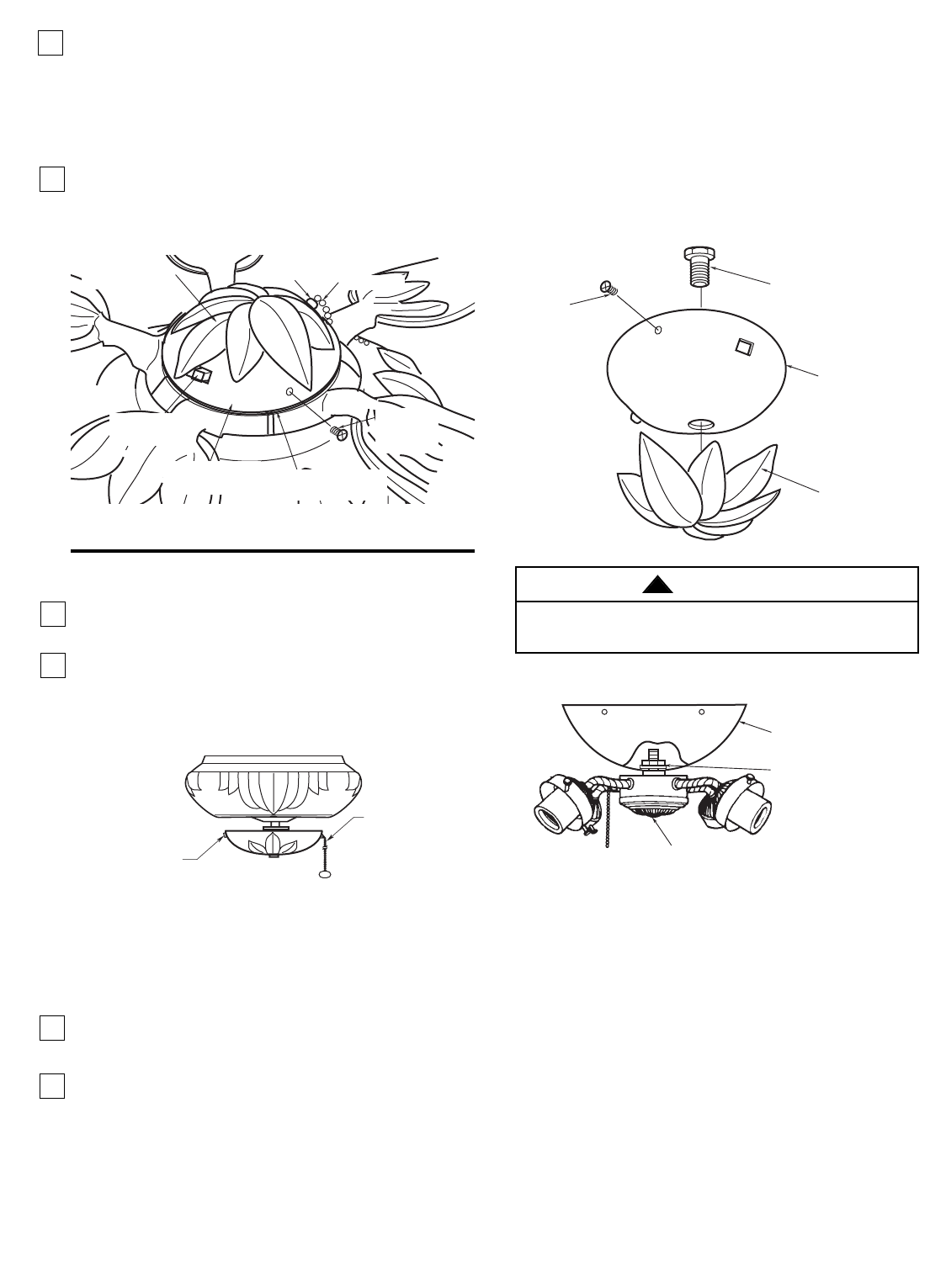
Attaching Light Kit
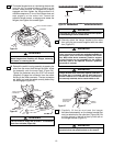
To install an Emerson accessory light kit, remove the
four screws securing the switch housing cover
assembly to the switch housing. Remove the trim
medallion from the bottom of the switch housing cover
(Figure 32). Attach the light kit to the switch housing
cover assembly with the lockwasher and nut supplied
with the light kit (Figure 33). Install the light kit in
accordance with the Emerson light kit Owner's
Manual.
12
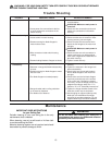
Using Your Ceiling Fan
1. Restore electrical power to the outlet box by turning
the electricity on at the main fuse box.
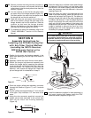
2. When controlled by a wall switch check the
operation of the fan by gently pulling on the
4-position speed control pull chain switch. The
operating sequence is as follows:
THREE-SPEED
1st Pull — HIGH
2nd Pull — Medium
3rd Pull — Low
4th Pull — OFF
3.When operated by an Emerson Remote Control,
check operation of fan and light in accordance with
the Remote Control Owner’s Manual.
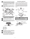
4. If airflow is desired in opposite direction, turn your
fan off and wait for the blades to stop turning. Then
slide the reversing switch to the opposite position
and turn fan on again. The fan blades will turn in
the opposite direction and reverse the airflow.
REVERSING
SWITCH
SPEED CONTROL
SWITCH PULL
CHAIN
REMOVE
TRIM
MEDALLION
REMOVE
FLAT HEAD
SCREW (4)
REMOVE
HEX
SCREW
SWITCH HOUSING
COVER ASSEMBLY
TRIM MEDALLION
BUSHING
SWITCH HOUSING
ASSEMBLY
SWITCH HOUSING
COVER ASSEMBLY
REVERSING
SWITCH LEVER
8-32 X 3/8"
FLAT HEAD
SCREW (4)
PULL CHAIN
Figure 31
Figure 32
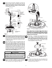
To avoid possible electrical shock, be sure electricity is
turned off at the main fuse box before wiring.
WARNING
!
SWITCH HOUSING
COVER ASSEMBLY
LIGHT KIT
LOCKWASHER AND NUT
(SUPPLIED WITH LIGHT KIT)
Figure 33
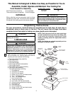
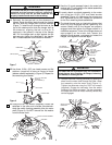
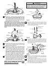
5. Slip the pull chain through the bushing in the switch
housing cover assembly (Figure 31). Position the
cover assembly on the switch housing assembly
with the reversing switch lever positioned in the slot
provided. Secure the cover assembly to the switch
housing assembly using four 8-32 x 3/8” flat head
screws (provided).
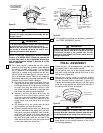
6. Slip the switch pull chain through the hole in the
pendant (supplied), then secure the pendant by
snapping the coupling (supplied) onto the end of
the chain.