


Your new ceiling fan will require a grounded electrical
supply line of 120 volts AC, 60 Hz, 15 amp circuit.
The outlet box must be securely anchored and capa-
ble of withstanding a load of at least 50 pounds.
If you feel that you do not have enough electrical
wiring knowledge or experience, have your fan
installed by a licensed electrician.
4
SECTION A
Assembly Instructions
for Installing the CF2500 Ceiling
Fan with a SW375 Receiver and a
SR330 Remote Control or with a
SW350 Wall Control
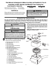
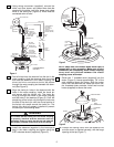
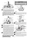
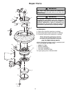
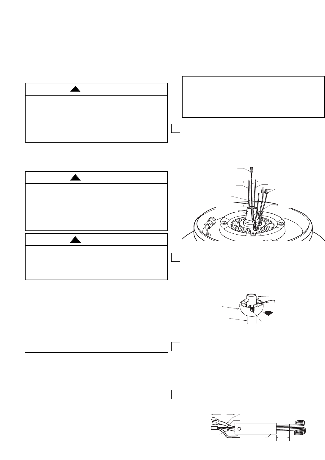
1. Cut the white, blue, and black wires about 3"
above the motor coupling (Figure 1). Strip insula-
tion 1/2" from end of wires and install a wire
connector on the black wire; this wire will not be
used. Remove the wire connectors from the red
and brown wires.
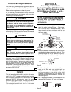
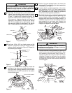
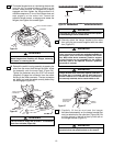
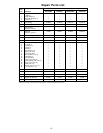
2. Loosen the setscrew in the hanger ball, slide the ball
down the downrod, and remove the clevis pin. Then
slide the hanger ball off the downrod (Figure 2).
Retain all parts for reinstallation in step 11.
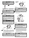
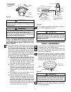
3. Push the wiring harness connector and the con-
nector on the blue wire (both supplied with the
SW375 Receiver and the SW350 Wall Control),
and the connector on the uplight yellow lead
assembly (supplied with the fan) through the
downrod until they all extend about 4” out of the
downrod (Figure 3).
4. Cut all wires approximately 3" from the end of the
downrod’. Strip insulation 1/2" from end of wires.
3"
WHITE WIRE
BLACK WIRE
BLUE WIRE
REMOVE WIRE
CONNECTORS
FROM RED AND
BROWN WIRES
INSULATE BLACK
WIRE USING WIRE
CONNECTOR
YELLOW
WIRE
MOTOR
COUPLING
MOTOR COUPLING SLOT
Figure 1
HANGER BALL
DOWNROD
CLEVIS PIN
SETSCREW
Figure 2
4"
DOWNROD
CUT HERE
3"
UPLIGHT YELLOW LEAD ASSEMBLY
WIRING
HARNESS
BLUE WIRE
Figure 3
IF THE CF2500 CEILING FAN IS BEING
INSTALLED WITH ANY OTHER CONTROL
METHOD, SKIP SECTION A AND GO TO
SECTION B TO BEGIN ASSEMBLY
INSTRUCTIONS.
Electrical Requirements
If your fan is to replace an existing ceiling light fixture,
turn electricity off at the main fuse box at this time and
remove the existing light fixture.
Uplight
This fan is supplied with a built-in uplight in the motor
housing. This uplight does not have a built-in switch to
turn it ON or OFF. A separate switch control must be
used to operate the uplight. This can be done with a
separate ON/OFF wall switch or one of the many
Emerson Fan/Light Controls, such as the SW375
Receiver, SR330 Remote Control or SW95L Controls.
The yellow lead supplied with this fan is the power
lead for the uplight.
To reduce the risk of fire, electric shock, or personal
injury, mount fan to outlet box marked acceptable for
fan support, and use screws supplied with outlet
box. Mos outlet boxes commonly used for support of
light fixtures are not acceptable for fan support and
may need to be replaced. Consult a qualified electri-
cian if in doubt.
WARNING
!
Turning off wall switch is not sufficient. To avoid
possible electrical shock, be sure electricity is
turned off at the main fuse box before wiring. All
wiring must be in accordance with National and
Local codes and the ceiling fan must be properly
grounded as a precaution against possible electrical
shock.
WARNING
!
To avoid fire, or shock, follow all wiring instructions
carefully.
Any electrical work not described in these
instructions should be done or approved by a
licensed electrician.
WARNING
!
The Emerson CF2500 Ceiling Fan is designed to be
operated from a SR330 Remote Control, from a
SW350 Wall Control with a SW375 Receiver, or from
other fan/light controls. There are no controls supplied
with the ceiling fan. If you are going to control your
ceiling fan with a SR330 Remote Control or with a
SW350 Wall Control, proceed to “SECTION A”. If you
are to control your ceiling fan in any other manner,
proceed to “SECTION B”.