


11
NOTE: If you are installing a SR330 Remote
Control or a SW350 Wall Control to operate the
fan and light, refer to the installation instructions
and wiring diagrams shown in Section A of this
Owner’s Manual.
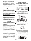
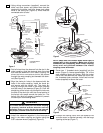
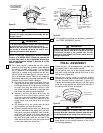
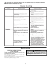
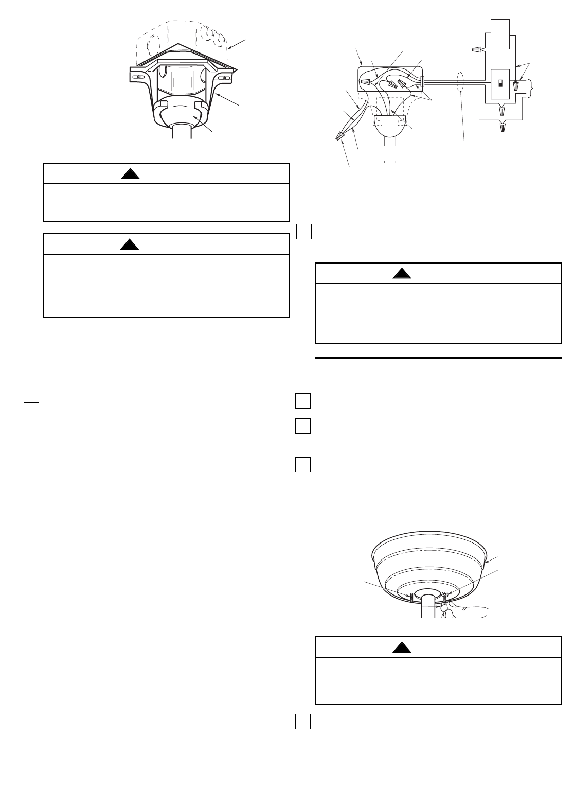
22. For a wall control installation you will need a
three-wire (with ground) conductor cable between
the ceiling and wall outlet boxes. This will allow
you to control the fan separately from the lights.
Figure 29 is a basic wiring diagram that will con-
trol the uplight and downlight on a switch and the
fan on a separate control. Refer to the installation
instructions and wiring diagrams supplied with the
Emerson Fan Control Owner’s Manual.
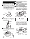
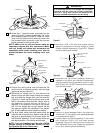
a. Connect the green grounding lead from the
hanger ball and the green grounding lead from
the hanger bracket to the grounding conductor
of supply (this may be a bare wire or a wire
with green colored insulation). Securely con-
nect wires with wire connector supplied.
b. Securely connect the white wire from the
downrod to the supply white (neutral) wire
using wire connector supplied. Securely con-
nect the black wire from the downrod to the
supply black (hot) wire using wire connector
supplied.
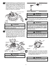
c. Cut terminal off of the yellow lead wire and
strip insulation 1/2” from end of wire.
d. Securely connect the blue wire and yellow wire
from the downrod to the supply red (hot) wire
using wire connector (supplied). After connec-
tions have been made, turn leads upward and
carefully push leads into the outlet box, with
the white and green leads on one side of the
outlet box and the black, blue and yellow leads
on the other side of the outlet box.
BLACK
BLACK FAN WIRE
LISTED OUTLET BOX
LIGHT
CONTROL
GREEN WIRE
(GROUND)
FROM
HANGER
BRACKET
TO 120
VOLT
SUPPLY
WHITE
GROUND
GROUND
GREEN WIRE (GROUND)
FROM HANGER BALL
LISTED WIRE CONNECTOR (4)
GROUND
WIRE
WHT.
EMERSON FAN CONTROL
BLACK
(HOT)
BLUE
RED
THREE - CONDUCTOR CABLE
WITH GROUND BETWEEN
CEILING AND WALL OUTLET
BOXES
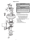
FINAL ASSEMBLY
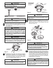
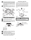
1. Screw the two 1-1/4” threaded studs (provided) into
the tapped holes in the hanger bracket.
2. Lift the ceiling cover up to the threaded studs and
turn until studs protrude through the holes in the
ceiling cover (Figure 30).
3. Secure the ceiling cover in place by sliding
lockwashers over the threaded studs and installing
the two knurled knobs (supplied). (Figure 30.)
Tighten the knurled knobs securely until the ceiling
cover fits snugly against the ceiling and the hole in
the ceiling cover is clear of the pipe.
4. Screw in three 40-watt (maximum) candelabra
base lamps into the uplight sockets on top of the
fan housing assembly.
Figure 29
1-1/4"
THREADED
STUD
LOCKWASHERS (2)
CEILING COVER
KNURLED KNOB
Figure 30
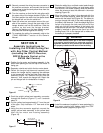
OUTLET
BOX
HANGER
BRACKET
HANGER BALL/
DOWNROD ASSEMBLY
NOTE: CEILING COVER,
SUPPLY WIRES AND
FAN WIRES OMITTED
FOR CLARITY.
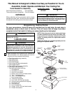
Figure 28
23. To complete the ceiling fan assembly, proceed to
the “FINAL ASSEMBLY” section.
To avoid possible fire or shock, do not pinch wires
between the hanger ball/downrod assembly and the
hanger bracket.
WARNING
!
To avoid possible electrical shock, be sure electricity
is turned off at the main fuse box before wiring.
NOTE: If you are not sure if the outlet box is ground-
ed, contact a licensed electrician for advice, as it
must be grounded for safe operation.
WARNING
!
Check to see that all connections are tight, including
ground, and that no bare wire is visible at the wire
connectors, except for the ground wire. Do not
operate fan until blades are in place. Noise and fan
damage could result.
WARNING
!
To avoid possible fire or shock, make sure that the
electrical wires are completely inside the outlet box and
not pinched between the ceiling cover and the ceiling.
WARNING
!