


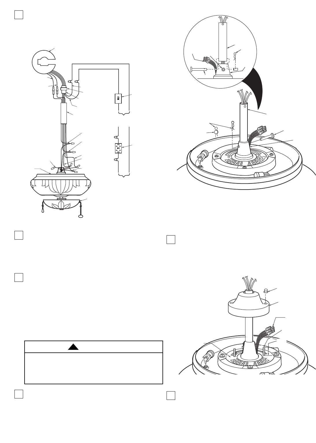
NOTE: Make sure the unused black motor lead is
capped with a wire connector. Make sure all wire
connectors are completely inside motor coupling
cover and not pinched between the motor
coupling cover and motor.
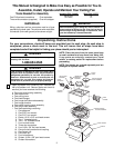
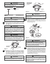
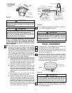
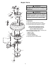
9. Screw two 1” threaded studs (supplied) into the
motor (Figure 6). Leave approximately 7/8” of the
stud extending above the motor. Slide the motor
cover over the downrod and rotate the cover until
the threaded studs protrude; install two knurled
knobs (supplied) to secure the cover.
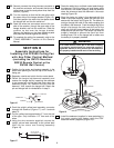
10. Position the ceiling cover over the downrod. Be
sure the cover is oriented correctly, with the large
opening at the top (Figure 7).
KNURLED KNOB
1" THREADED
STUD
MOTOR
COUPLING
COVER
WIRE
CONNECTORS
7/8"
MOTOR
Figure 6
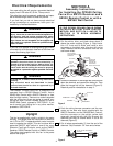
SETSCREW
CLEVIS PIN
MOTOR
COUPLING
DOWNROD
HAIRPIN
CLIP
MOTOR
COUPLING
HAIRPIN
CLIP
CLEVIS
PIN
DOWNROD
LEADS TO BE
POSITIONED IN
SLOT IN MOTOR
COUPLING
CLEVIS
PIN
Figure 5
5
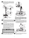
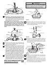
5. Using wiring connectors (supplied), connect the
white, red, blue, brown, and yellow wires from the
downrod to the white, red, blue, brown and yellow
wires of the ceiling fan (Figure 4). Wires must be
connected color-to-color.
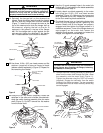
6. Fold all wires from the downrod into the slot in the
motor coupling, slide the downrod down the wires
and seat the downrod in the motor coupling. All
wires and wire connectors should be placed
through the motor coupling slot beneath the down-
rod (See Figure 5).
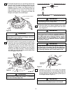
7. Align the clevis pin holes in the downrod with the
holes in the motor coupling. Install the clevis pin
and secure with the hairpin clip. The clevis pin
must go through the holes in the motor coupling
and the holes in the downrod (Figure 5). Push the
straight leg of the hairpin clip through the hole near
the end of the clevis pin until the curved portion of
the hairpin clip snaps around the clevis pin. The
hairpin clip must be properly installed to prevent
the clevis pin from working loose.
8. Install the setscrew (supplied in the loose parts
bag) in the motor coupling and tighten using the
5/32” setscrew wrench (supplied) (Figure 5).
FAN BLADES REMOVED
FOR CLARITY
DOWNROD
BLACK WIRE
WHITE WIRE
WIRING HARNESS
CONNECTOR
YELLOW WIRE
TO YELLOW
WIRE
BLUE WIRE
TO
BLUE WIRE
SW375 RECEIVER
BROWN WIRE
TO BROWN WIRE
YELLOW WIRE
TO YELLOW WIRE
LISTED GENERAL
USE ON/OFF
WALL SWITCH
(MUST BE
USED WITH SR330
REMOTE CONTROL)
RECEIVER
CONNECTOR
RED WIRE
TO RED WIRE
WHITE WIRE
TO WHITE WIRE
BLACK WIRE
(NOT USED)
BLUE WIRE
TO BLUE WIRE
BLACK WIRE
WHITE WIRE
BLACK
WIRE
WHITE
WIRE
BLACK
WHITE
BLACK
SW350
WALL
CONTROL
FAN
HOUSING
TO
120V SUPPLY
TO
120V SUPPLY
LIGHT FIXTURE
Figure 4
It is critical that the clevis pin in the motor coupling
is properly installed and the setscrew securely
tightened. Failure to verify that the pin and setscrew
are properly installed could result in the fan falling.
WARNING
!