


6
U.L. Model No.: CF230
Installation of Blades & Light Assembly
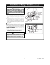
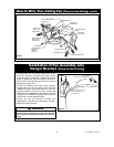
10-24 x 5/16" FLANGE
HEAD BLADE SCREW
(3 Per Blade)
FAN BLADE
FAN BLADE
FLANGE
Figure 4
1. Mount the blade flanges to the fan blades using
three #10-24 x 5/16” Phillips blade screws per
blade (supplied) (Figure 4). Repeat for the three
remaining blades.
To reduce the risk of personal injury, do not bend the
blade flange when installing the blade flanges,
balancing the blades or cleaning the fan. Do not
insert foreign objects in between rotating fan blades.
WARNING
!
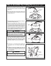
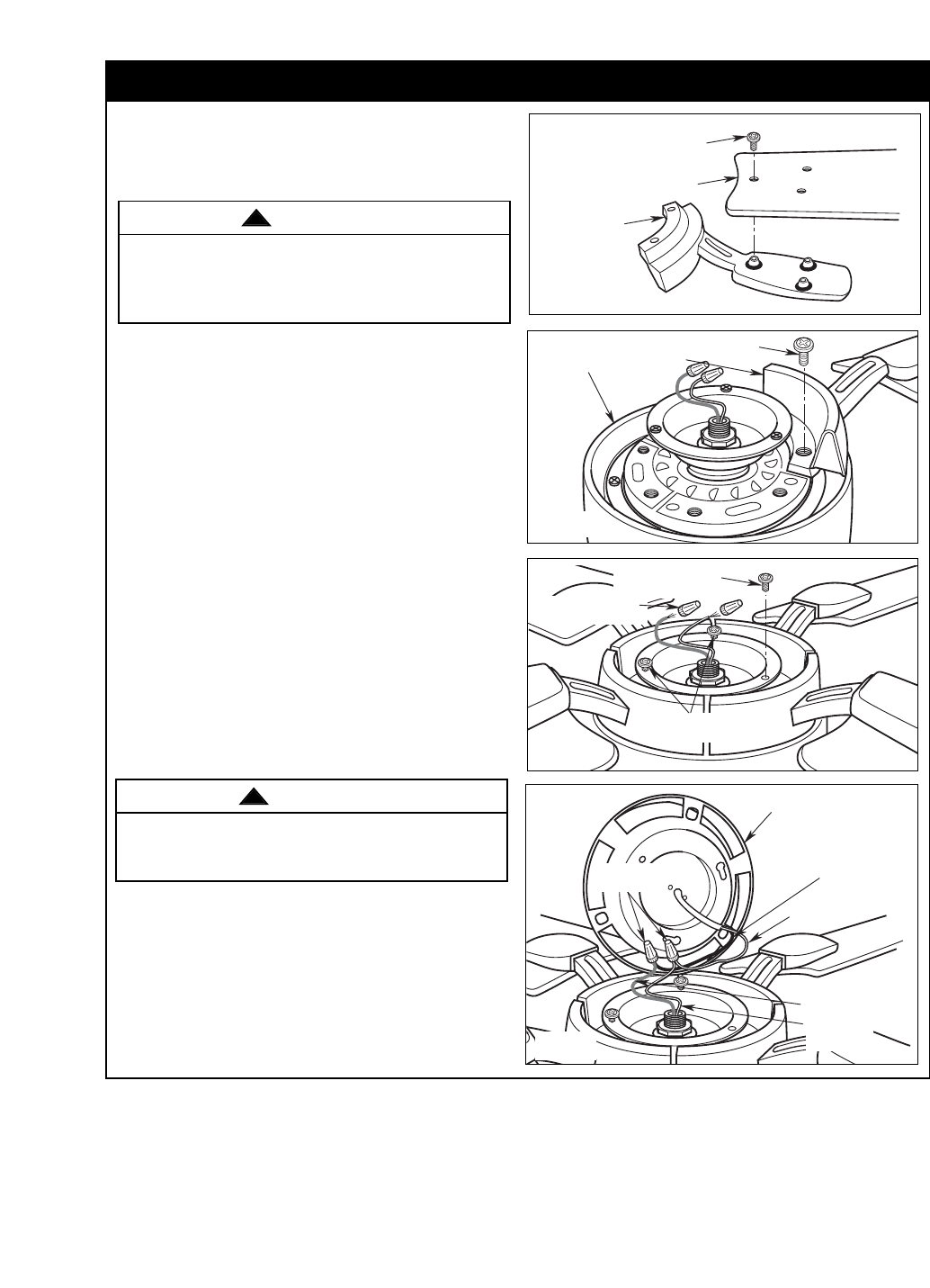
LIGHT KIT PLATE
ASSEMBLY
LIGHT SWITCH
BLACK WIRE
LIGHT SWITCH
WHITE WIRE
FAN MOTOR
WHITE WIRE
FAN MOTOR
BLUE WIRE
REINSTALL WIRE
CONNECTORS
Figure 7
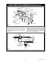
4. Remove and retain the wire connectors from the
white and blue wires (Figure 6).
5. Connect the white wire from the ceiling fan to the
white wire of the light kit plate (Figure 7). Connect
the blue wire from the ceiling fan to the black wire
of the light kit plate. Use wire connectors
(previously removed) to make connections.
NOTE: Carefully tuck all wires and connectors
into the fan motor assembly.
To avoid possible fire or shock, make sure that
electrical wires are not pinched between the light kit
plate assembly and the fan motor assembly.
WARNING
!
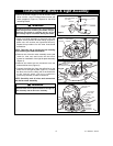
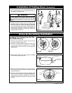
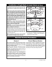
2. Attach one blade assembly to the motor using the
captive screw provided for each flange (Figure 5).
Make sure the screws are tightened securely.
Repeat this procedure for the other three blade
assemblies.
NOTE: Take care not to scratch the fan housing
when installing the blade assemblies.
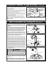
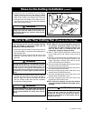
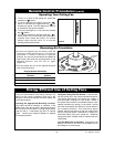
3. Remove one of the fan motor assembly screw (and
retain for later use) and loosen the two other
screws for installation of the light kit plate assembly
(Figure 6).
CAPTIVE SCREW
MOTOR
HOUSING
BLADE FLANGE
ASSEMBLY
Figure 5
LOOSEN TWO FAN
MOTOR SCREWS
REMOVE AND RETAIN
FAN MOTOR SCREW
REMOVE AND RETAIN
WIRE CONNECTORS (2)
Figure 6