


14
U.L. Model No.: CF230
Remote Control Procedures
General
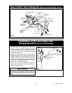
Your Emerson Ceiling Fan/Light Remote Control
consists of hand-held transmitter and a receiver which
is mounted under the fan ceiling cover. The remote
control is designed to separately control your ceiling
fan speed and light intensity.
The remote control transmitter is powered by two AAA
alkaline batteries (included). To prevent possible
damage if the batteries should leak, be sure to
remove the batteries when the control is not to be
used for an extended period of time.
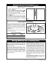
Code switches in the transmitter and receiver may be
set in 32 different positions. If your fan and light go on
and off without using your control, you may be getting
interference from other remote units such as garage
door openers, car alarms or security systems. To
remedy this situations, simply change the combination
code in your transmitter and receiver.
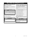
Preset Memory Feature
Your Emerson receiver is equipped with a preset
memory feature. If the AC supply to the receiver is
powered through a wall switch, when the switch is
turned OFF, the control will remember the light
intensity and fan speed. When the switch is turned
back ON the light and fan will resume operation as
they were prior to the switch being turned OFF.
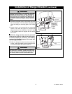
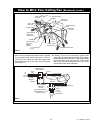
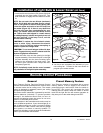
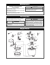
Installation of Light Bulb & Lower Cover (All Fans)
1. Install the 50-watt (maximum) GU10 base light bulb
(supplied) into the light socket (Figure 25). Turn
bulb clockwise to engage into the socket for secure
fit.
NOTE: Do not touch the new 50-watt (maximum)
MR-16, GU-10 bulb with your bare fingers; using a
cloth or soft gloves to hold the bulb, gently push
it into the socket and twist to lock the lamp into
the socket (Figure 25). If there is any doubt that
the bulb may have been contaminated by your
touch, you should clean the bulb before its first
use. Take a clean cloth dipped in a small amount
of rubbing/isopropyl alcohol and gently brush off
the bulb surface. If the lamp is hot, wait 30
minutes before cleaning.
CAUTION: To reduce the risk of electric shock,
burns or other injury, disconnect the electric
supply circuit to the fan before attempting to
install or replace the halogen bulb.
CAUTION: To not touch halogen bulbs with bare
hands. Fingerprints may result in shorter bulb life.
Remove fingerprints with alcohol.
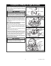
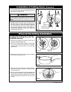
2. Place the lower cover into the opening in the light
kit plate assembly. Place the three pins on the light
kit plate assembly into the three mounting holes
located on the underside of the lower cover. Turn
the lower cover clockwise until it stops and locks
into place (Figure 26).
NOTE: Periodically check that the cover is seated
fully clockwise in the light kit plate assembly.
50-WATT GU10
BASE LIGHT BULB
Figure 25
LOWER
COVER
LOWER COVER
PIN (3)
LIGHT SWITCH
PIN (3)
Figure 26
3. You have now completed the assembly of your
new ceiling fan. Proceed to the next section to
program your remote controls.