


3
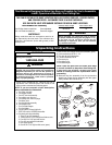
Unpacking Instructions
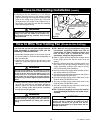
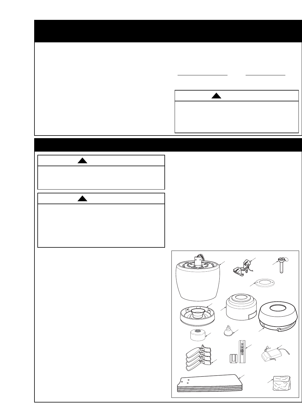
1. Open carton containing fan. Remove top half of
styrofoam unit. Remove parts and check to see
that you have received the following parts:
NOTE: If you are uncertain of part description,
refer to exploded view illustration.
This Manual Is Designed to Make it as Easy as Possible for You to Assemble,
Install, Operate and Maintain Your Ceiling Fan
Tools Needed for Assembly
One Phillips head screwdriver One stepladder
One 1/4” blade screwdriver One wire stripper
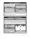
MATERIALS
Wiring outlet box and box connectors must be of
type required by the local code. The minimum wire
would be a 3-conductor (2-wire with ground) of the
following size:
Installed Wire Length Wire Size A.W.G.
Up to 50 ft. 14
50-100 ft. 12
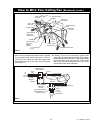
Before assembly your ceiling fan, refer to section
on proper method of wiring your fan (page 9 or 12).
If you feel you do not have enough wiring
knowledge or experience, have your fan installed
by a licensed electrician.
Do not install or use fan if any part is damaged or
missing. Call Toll-Free:
1-800-654-3545
This product is designed to use only those parts
supplied with this product and/or any accessories
designated specifically for use with this product by
Emerson Electric Co. Substitution of parts or
accessories not designated for use with this product
by Emerson Electric Co. could result in personal
injury or property damage.
j.
g.
h.
i.
k.
m.
l.
l.
f.
a.
b.
c.
d.
e.
WARNING
!
WARNING
!
WARNING
!
NOTE: Place the parts from the loose parts bags
in a small container to keep them from being lost.
If any parts are missing, contact your local
retailer or catalog outlet for replacement before
proceeding.
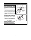
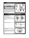
2. Remove the fan assembly from the protective
plastic bag. Place the fan assembly into the upper
foam pad with the lead wires up.
a. Fan motor assembly
b. One hanger bracket
c. One 4.5” downrod assembly
d. One ceiling cover trim ring
e. One ceiling cover with trim plugs
f. One lower cover
g. One light kit plate assembly
h. One coupler cover
i. Four fan blade flanges
j. Four fan blades
k. One 50 watt GU10 base light bulb
l. RCFP-190 receiver & SR400 transmitter
m.One loose parts bag containing:
1. Three 12 ga. wire connectors
2. Thirteen #10-24 x 5/16" flange head blade screws
3. Four #10-24 x 3/16" pan head screws
4. Four #10 external tooth lockwasher
5. One rubber gasket
6. One #8-32 x 5/16” light switch screw (spare)
THIS FAN IS SUITABLE FOR DAMP LOCATIONS SUCH AS COVERED PORCHES, COVERED PATIOS,
AND COVERED DECKS...ANYWHERE THERE IS A ROOF OVERHEAD.
USE ONLY WITH LIGHT KITS MARKED SUITABLE FOR USE IN DAMP LOCATIONS.
7. One 1/4-20 x 9/16” flange screw with lockwasher (spare)
8. Two threaded stud, #8-32 x 1-1/4”
9. Two external tooth lockwashers
10. Two knurled knobs, #8-32
11. One clevis pin
12. One hairpin clip
13. One balancing kit
U.L. Model No.: CF230