


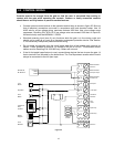
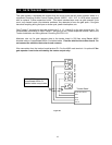
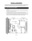
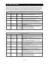

2.8 TERMINAL IDENTIFICATION AND DESCRIPTION
2.8.1 MAIN TERMINAL
1. RADIO RECEIVER LOW VOLTAGE COMMON
2. RADIO RECEIVER FULL OPEN INPUT
3. RADIO RECEIVER 24 VAC POWER – 250-ma MAX
4. FULL OPEN / CLOSE INPUT
When gate is closed, input will open gate to full position.
When gate is open and auto close timer is turned on, input will re-set and hold timer.
When gate is open and auto close timer is turned off, input will close gate.
When gate is closing, input will reverse gate.
5. 14-FOOT OPEN / CLOSE INPUT
When gate is closed, input will open gate to 14-foot position.
When gate is open and auto close timer is turned on, input will re-set and hold timer.
When gate is open and auto close timer is turned off, input will close gate.
When gate is closing, input will reverse gate to 14-foot position.
6. STANDARD REVERSE INPUT
When gate is fully closed or in the opening cycle, this input has no affect on the gate
operator.
When gate is open and auto close timer is turned ON, input will re-set and hold timer.
When gate is open and auto close timer is turned OFF, input will prevent gate from
closing.
When gate is closing, input will reverse gate if SW 2, switch 2 is OFF.
When gate is closing, input will stop gate if SW 2, switch 2 is ON.
7. NOT USED
8. OPEN INPUT - Use with DoorKing 3 button control station only (P/N 1200-006).
9. CLOSE INPUT - Use with DoorKing 3 button control station only (P/N 1200-006).
10. OPEN LOOP LOGIC OUTPUT
If SW 1, switch 1 is OFF, this terminal becomes the logic output of the loop detector
plugged into the OPEN loop port (DoorKing loop detectors only).
11. ALARM RESET INPUT
12. ALARM OUTPUT
13. GATE TRACKER - BUSY
14. GATE TRACKER - DATA
15. DRY RELAY CONTACT
Operation of relay is dependent on setting of SW 1, switches 4 and 5. Relay contacts
can be set for Normally Open (NO) or Normally Closed (NC) operation. Contact
rating is 1 amp maximum at 24 Volts.
16. DRY RELAY CONTACT
17. LED INDICATOR OUTPUT - Provides 24 VDC, 250-ma maximum to power LED.
Operation of LED is dependent on setting of SW 1, switches 4 and 5.
18. LOW VOLTAGE COMMON
23