


2.5 GATE TRACKER™ CONNECTIONS
This gate operator is equipped with outputs from the circuit board that will report operator status to a
companion DoorKing Access Control System (Model 1803PC, 1815, 1817 or 1818) when equipped
with an optional Tracker expansion board. This report includes items such as gate operator cycle
count, any shorted inputs, loop detector problems, any attempts to force the gate open, if the gate
has struck anything during the open or close cycle, power interruptions, etc.
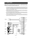
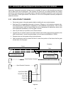
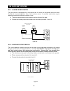
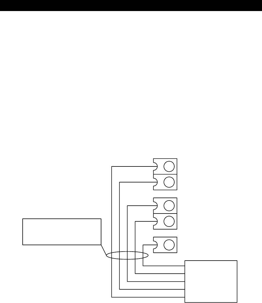
Gate Tracker™ connections are made at terminals 3, 4, 13, 14 and 18 on the main terminal strip. For
more detailed information on Gate Tracker™ and wiring to the Tracker expansion boards, refer to the
Tracker Installation and Wiring Manual, DoorKing P/N 2351-010.
Maximum wire run for gate operator data to the tracker board is 500 feet using Belden #9931
shielded cable or Consolidated #5324-CL shielded cable. Float the shield at the tracker board. Do
not connect the shield to the tracker board common.
Wire connection from the tracker board terminal P1-5 to the 4602 main terminal 4 is optional if the
gate operator is not to be activated by the tracker output relay.
3
4
18
13
14
P1-6, P2-5 and 11
P2-1
P2-2
P1-5
P2-12
4602 Board Terminals
Tracker Board
Belden #9931 or
Consolidated #5324-CL
shielded cable or equivalent.
Figure 29
19