


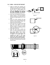

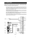
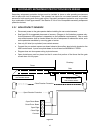
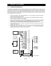

2.2 CONTROL WIRING
Controls must be far enough from the gate so that the user is prevented from coming in
contact with the gate while operating the controls. Outdoor or easily accessible controls
should have a security feature to prevent unauthorized use.
• Connect optional control devices to the operator terminal strip as shown in figure 25. Be sure
that all electrical connections are made in accordance with local electrical codes. Use 18
AWG wire for all low voltage wiring, maximum distance 3000 feet. Use a low voltage surge
suppresser, DoorKing P/N 1878-010 if low voltage wire runs exceed 1000 feet. All inputs to
the terminal strip must be NORMALLY OPEN.
• Standard reversing input (term 6) only functions while the gate is in the closing cycle and
should not be used as an input for a secondary entrapment protection device. See Section
2.3 for secondary entrapment protection device wiring.
• Do not power any devices from the circuit board other than a low voltage radio receiver as
shown. Power available at terminal 3 is limited to 250 ma at 24 VAC. Three-button control
station must be DoorKing P/N 1200-006 only. Others will not work.
• If the 14-foot partial open feature is used, connect those devices that are to open the gate 14
feet to terminal 5 as indicated by the dotted lines. The Fire Department access switch should
always be connected to the full open input.
1
2
3
4
5
6
7
8
9
18
Push
Button
Keyswitch
Lock
Boxes
Telephone
Entry
Systems
Digital
Keypad
Card
Readers
3 Button
Control
Photocell
Radio Receiver
Common
Radio Receiver
Full Open Input
Radio Receiver
24 VAC Pwr
Full Open
14 Ft Open
Not
Used
Standard
Reverse
Open Only
Common
Close Only
OPEN
CLOSE
STOP
Fire
Dept
Common
Relay
Power
MicroPLUS
RF Receiver
Figure 25
15