


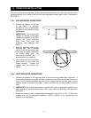


2.1 HIGH VOLTAGE CONNECTIONS
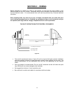
Use Table 1 to determine high voltage wire size requirements. The distance shown in the chart is
measured in feet from the operator to the power source. If power wiring is greater than the maximum
distance shown, it is recommended that a service feeder be installed. When large gauge wire is used,
a separate junction box must be installed for the operator connection. The wire table is based on
stranded copper wire. Wire run calculations are based on a 110 VAC power source with a 3% voltage
drop on the power line, plus an additional 10% reduction in distance to allow for other losses in the
system.
WIRE SIZE / DISTANCE IN FEET MODEL AMPS
12 AWG 10 AWG 8 AWG 6 AWG
9100 SINGLE 5.4 170 275 460 685
9100 DUEL 10.8 85 135 230 340
Table 1
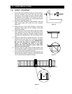
Conduits
ON-OFF Switch
Incoming
Power Wires
115 VAC HOT
115 VAC NEU
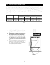
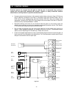
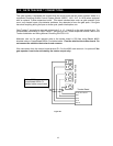
• Route incoming high voltage power through
conduit and into the operator as shown in
figure 24.
• Be sure wiring is installed in accordance with
local codes. Be sure to color code all wiring.
• Connect the power wires to the high voltage
terminal strip as shown; BLACK to 115 VAC
HOT, WHITE to 115 VAC NEU and GREEN
to GROUND LUG located next to the terminal
strip.
• It is recommended that a surge suppresser be
installed on the high voltage power lines to
help protect the operator and circuit board
from surges and power fluctuations.
Figure 24
14