


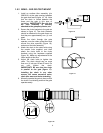
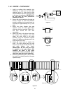

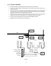
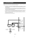
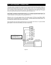
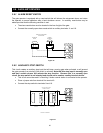
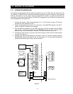
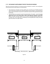

2.3.2 CONTACT SENSORS
• Disconnect power to the gate operator before installing the contact sensors.
• Connect the contact sensors as shown below to the auxiliary terminal strip located on the
4602 control board.
• Contact sensors must be located at the leading edge, trailing edge, and post mounted both
inside and outside of the vehicular sliding gate. Additional contact sensors may be added for
additional protection where an entrapment zone may exist.
• Hardwired contact sensors must be located and wiring arranged so that the communication
between the sensor and the gate operator is not subjected to mechanical damage.
• Inputs from sensing edges/receiver to circuit board are NORMALLY OPEN.
• Diagram does not show power wiring to RF receiver.
Roadway
Fence
Gate
Open Photo-Beam
Close Photo- Beam
Open Edge
Close Edge
Common
Trailing
Edge
Leading
Edge
Inside
Post Mount
Outside
Post Mount
Lead
Edge
TX
Trail
Edge
TX
Trail Edge
Lead Edge
2 CH
Rec'vr
Inside Post
Outside Post
Trailing
edge
relay
Leading
edge
relay
Fi
g
ure 27
17