


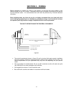
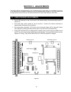

2.7 MASTER / SLAVE WIRING
2.7.1 OPERATOR INTERFACE
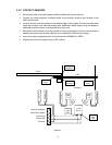
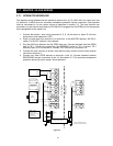
The interface wiring between the two operators requires four (4) 18 AWG wires for control plus two
(2) additional 18 AWG wires for secondary entrapment protection device connection. Each operator
must be connected to it's own power source as described in section 2.2. The loop functions are
controlled by a two-channel loop detector (P/N 9404-010) plugged into the OPEN port on the operator
that is designated as the master unit.
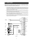
1. Connect the master / slave wiring (terminals 4, 5, 6, 18) as shown in figure 32. Be sure
that power to both operators is OFF.
2. Place a jumper wire from terminal 10 to terminal 4 in the MASTER operator. Set SW 2,
switch 1 to the OFF position in this operator.
3. Plug the 9405 loop detector into the OPEN loop port. Connect the leads from the OPEN
loop to TB 1. Connect the leads from the REVERSE loop(s) to TB 2. Connect TB 3
Normally Open (N.O.) to terminal 6. Connect TB 3 Common (C) to terminal 18.
4. Connect the radio receiver as shown. Note that the relay contact from the radio receiver
connects to terminal 4.
5. Connect any other OPEN devices to terminals 4 and 18. Connect standard external
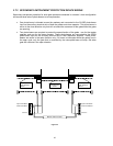
REVERSING devices to terminals 6 and 18. See section 2.7.2 for secondary entrapment
protection device wiring for master / slave operators.
1
10
18
6
4
5
18
Master Operator
Slave Operator
Connect Chassis Ground To
Chassis Ground (Green Wire)
2
3
4
5
6
Common
Relay
Power
TB 1
TB 2
TB 3
9505
Detector
Open Loop
Reverse Loop(s)
Orange
Brown
Violet
YellowYellow
Violet
Brown
Orange
Aux
Terminal
Strip
Master / Slave Conduit
NOTE
: Auxiliary
terminals used is
dependent on the type
of secondary
protection used.
Figure 32
21