


2.3 SECONDARY ENTRAPMENT PROTECTION DEVICE WIRING
Secondary entrapment protection devices must be installed to insure a safe operating environment
and to reduce the risk of entrapment. This operator has inputs for non-contact sensors and contact
sensors for both opening and closing gate cycles. Secondary entrapment protection may be provided
by a combination of both type sensors. See Section 5.3 for a list of acceptable secondary entrapment
protection devices.
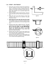
2.3.1 NON-CONTACT SENSORS
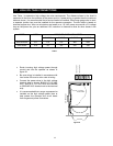
• Disconnect power to the gate operator before installing the non-contact sensors.
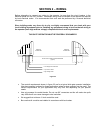
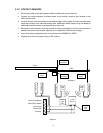
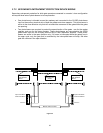
• See figure 26 for suggested placement of sensors. (Diagram is for illustration purposes only.
Actual placement of the sensors is dependent on the installation requirements). One or more
non-contact sensors shall be located where the risk of entrapment or obstruction exists, such
as the perimeter reachable by a moving gate or barrier.
• Use only UL listed (or equivalent) non-contact sensors.
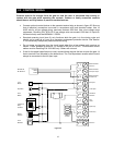
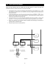
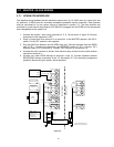
• Connect the non-contact sensors as shown below to the auxiliary terminal strip located on the
4602 control board. Inputs from photo-beam to circuit board are NORMALLY OPEN.
• Diagram does not show power wiring to photo-beams.
• Open photo-beam must be placed so that it covers that portion of the fence that the gate
covers when it is fully open.
Roadway
Fence
Gate
Open direction
non-contact sensor
Close direction
non-contact sensor
Open Photo-Beam
Close Photo- Beam
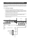
Open Edge
Close Edge
Common
Close Direction Protection
Open Direction Protection
Fi
g
ure 26
16