


9
to the repair being performed - see Table of Contents
for page number.
Once repair is complete, reassemble in the reverse 5.
order as above.
LED LIGHT STRIPS REPLACEMENT
WARNING: Disconnect power before attempting any
maintenance or cleaning to reduce the risk of electric
shock or damage to persons.
CAUTION: If unit was operating prior to servicing allow
at least 10 minutes for lights and heating elements to cool
off to avoid accidental burning of skin.
Tools required: Phillips head screwdriver
Wire snips
CAUTION: Follow “Preparation for Service” instructions
before proceeding.
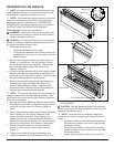
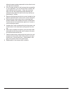
Partially release the lower face panel, by removing 1.
the screw on the left side and on the right side of the
panel, inside the unit. Pull the front panel forward from
the topside by approximately 2” inches. There are 3
additional screws located underneath the front face but
do not need to be removed. There should be enough
“give” to allow the panel to pull slightly forward.
!
NOTE: If the 3 bottom screws to the front panel are
accessible in your application, you can remove them to
obtain the most clearance for the repair. If they are not ac-
cessible, you can still proceed with them attached.
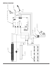
Remove the electrical junction box cover located on the 2.
bottom right hand side by removing the screw on the
front of the cover. Lift the cover out and set aside.
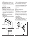
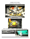
Remove the icker rod by slightly bending the rod and 3.
pulling the rubber bushing off the motor arm located on
the bottom right. Remove the middle plastic bushing
by lifting it up off the center bracket. Slide the remain-
der of the icker rod off the end bracket on the left.
CAUTION: When removing and replacing the icker
motor try to keep any slight bending of the icker rod
minimal so as to not damage it. If icker rod is damaged, it
should be replaced to ensure proper operation.
On the top right side, just below the Remote Switch-4.
board, remove the 2 screws that secure the upper
control panel cover. Remove the cover and set aside
to allow access to the LED Driver Board wires.
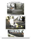
On the LED Driver Board (smaller board on the right), 5.
remove the two (2) orange wire connectors and sepa-
rate the wires - noting original conguration.
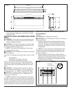
In the lower area of the replace, remove the 2 screws 6.
on each LED light strip, which secure the strips to the
light strip covers.
Cut and remove plastic cable ties that hold the wires in 7.
place from the LED light cover at the bottom and up to
the LED Driver Board at the top.
Gently pull the LED light strip wires up and around from 8.
the side of the light covers to free the strips. The cov-
ers may require a small amount of pressure upward, to
allow a little “give” when feeding the wires around the
covers.
Lift and remove LED strips out of the light covers and 9.
slide the wires out of the protective insulation.
Feed the wires from the new LED strip back through 10.
the same protective insulation up to the LED Driver
Board.
Attach the new LED strips to the LED cover with the 11.
screws from step 9.
Route wires around the light covers and re-attach the 12.
covers with the screws from the outer bottom panel of
the replace.
Reconnect the wires at the LED Driver Board at the top 13.
using the 2 orange wire connectors from STEP 6.
Route wires back into control panel area.14.
Reassemble in the reverse order as above.15.
LED DRIVER BOARD REPLACEMENT
WARNING: Disconnect power before attempting any
maintenance or cleaning to reduce the risk of electric
shock or damage to persons.
CAUTION: If unit was operating prior to servicing allow
at least 10 minutes for lights and heating elements to cool
off to avoid accidental burning of skin.
Tools required: Phillips head screwdriver
Needle nosed pliers
Wire snips
CAUTION: Follow “Preparation for Service” instructions
before proceeding.
On the top right side, just below the Remote Switch-1.
board, remove the 2 screws that secure the upper
control panel cover. Remove the cover and set aside
to allow access to the LED Driver Board wires.
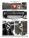
Remove the two (2) cable ties on the right to allow ac-2.
cess to the wires of the LED Driver Board.
On the LED Driver Board (smaller board on the right), 3.
remove the two (2) orange wire connectors and sepa-
rate the wires - noting their original conguration.
Also on the LED Driver Board remove the 2 wire con-4.
nectors that join the 2 white wires together and the two
black wires together.
To remove the Driver Board off the plastic mounts, 5.
pinch the plastic mounting tabs with needle nose pliers.
Pull the old board off.
Connect the rebox wires onto the new LED Driver 6.
Board. Spread the ange on the top of the plastic
mounting tabs apart and re-use them to re-secure
the new Driver Board into the replace. Line up the
holes on the Driver Board and gently press the new
board onto the mounts. Make sure the Driver Board is
secure.
Reassemble in the reverse order as above.7.