


10 www.dimplex.com
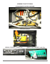
FLICKER MOTOR/FLICKER ROD
REPLACEMENT
WARNING: Disconnect power before attempting any
maintenance or cleaning to reduce the risk of electric
shock or damage to persons.
CAUTION: If unit was operating prior to servicing allow
at least 10 minutes for lights and heating elements to cool
off to avoid accidental burning of skin.
Tools required: Phillips head screwdriver.
CAUTION: Follow “Preparation for Service” instructions
before proceeding.
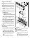
Partially release the lower face panel, by removing 1.
the screw on the left side and on the right side of the
panel, inside the unit. Pull the front panel forward from
the topside by approximately 2” inches. There are 3
additional screws located underneath the front face but
do not need to be removed. There should be enough
“give” to allow the panel to pull slightly forward.
!
NOTE: If the 3 bottom screws to the front panel are
accessible in your application, you can remove them to
obtain the most clearance for the repair. If they are not ac-
cessible, you can still proceed with them attached.
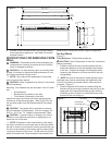
Remove the electrical junction box cover located on the 2.
bottom right hand side by removing the screw on the
small mounting-ange on the front face of the junction
box cover. Lift the cover out and set aside. Once the
cover is removed, the icker motor and terminal block
will now be visible.
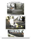
Remove the icker motor wires from the terminal block 3.
by removing the 3 small Philips screws holding each
wire in place then gently pulling the wires out of the
terminal block - noting their original locations.
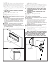
Remove the 2 screws holding the icker motor to the 4.
mounting bracket. Gently pull the motor away from the
icker rod.
CAUTION: When removing and replacing the icker
motor try to keep any slight bending of the icker rod
minimal so as to not damage it. If icker rod is damaged, it
should be replaced to ensure proper operation.
Properly orient the new icker motor onto the motor 5.
bracket and re-attach with the 2 mounting screws.
Reassemble in the reverse order as above.6.
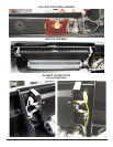
ELEMENT REPLACEMENT
WARNING: Disconnect power before attempting any
maintenance or cleaning to reduce the risk of electric
shock or damage to persons.
CAUTION: If unit was operating prior to servicing allow
at least 10 minutes for lights and heating elements to cool
off to avoid accidental burning of skin.
Tools required: Phillips head screwdriver.
Needle nosed pliers.
Wire Snips
3/8” ratchet or wrench
CAUTION: Follow “Preparation for Service” instructions
before proceeding.
Remove the 4 screws that secure the angled switch 1.
housing cover located just below the Remote Switch-
board on the top right. Remove cover and set aside.
Remove the front panel that spans across the top front 2.
facia. To do so, locate the 4 screws: 2 on the left and
2 right on the angled part behind the facia. Wires from
the switch housing are connected to this piece so care-
fully move it farther down in the body of the unit, to give
some room to access the heating assembly cover.
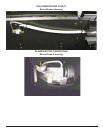
Remove the heating assembly cover in the top center 3.
by removing the 10 screws on the side brackets: 5 on
the left and 5 on the right. Wires from the switch hous-
ing are connected to this piece, so carefully move it
farther down in the body of the unit, to give some room
to access the heating assembly housing.
Release the top panel of the heating assembly hous-4.
ing by removing 4 screws on the side brackets. Pull
the top panel of the heating assembly housing out from
between the brackets.
From the top panel of the heating assembly housing, 5.
remove the 4 screws that hold the element cover to the
housing panel.
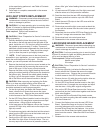
Disconnect wires from the ends of the elements noting 6.
their original locations.
!
NOTE: Using a at head screwdriver gently pry be-
tween the end of the connectors and the element to release
the wires.
!
NOTE: Some of the wires may have a “piggy-back”
connector that allows a second wire to connect to the same
prong as the rst wire. Try and keep the “piggy-back” con-
nection together when pulling the wires off the element.
Using a 3/8” ratchet or wrench remove the hex head 7.
screw from both sides of the element. Remove ele-
ments from the element housing and replace with the
new elements.
Reassemble in the reverse order as above.8.
CAUTION: When re-installing covers and panels, be
sure the wires are guided and tucked into the proper open-
ings along the right side so they are not pinched and allows
enough space to reinstall panel.
HIGH TEMPERATURE CUTOUT
REPLACEMENT
WARNING: Disconnect power before attempting any
maintenance or cleaning to reduce the risk of electric
shock or damage to persons.
CAUTION: If unit was operating prior to servicing allow
at least 10 minutes for lights and heating elements to cool
off to avoid accidental burning of skin.
Tools required: Phillips head screwdriver
Needle nosed pliers
Wire Snips